Download
1 / 30
300 likes | 688 Vues
ISM Band Transmitter/Receiver. Bob Sosack Chris Lettow Justin Quek TA: Julio Urbina July 27, 2001. Introduction . Project created for Aerial Robotics Club – Develop main communication link between airplane and ground base station Design system to work in ISM Band (902-928 MHz)

E N D
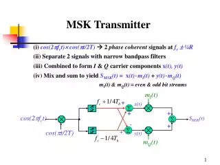
ISM Band Transmitter/Receiver • Bob Sosack • Chris Lettow • Justin Quek • TA: Julio Urbina • July 27, 2001
Introduction • Project created for Aerial Robotics Club – Develop main communication link between airplane and ground base station • Design system to work in ISM Band (902-928 MHz) • RF system consists of microcontroller-driven transceiver chip, a power amplifier, and transmit and receive antennas
Project Features and Goals • Transmit and receive ISM Band signals • High power transmission with low power consumption • Obtain at least 11.6 dB gain in the power amplifier • Antennas have 2:1 VSWR Bandwidth in entire ISM Band (902-928 MHz)
Signal Generation and Modulation – The Transceiver Chip • Texas Instruments TRF6900A transceiver chip • Modulator on chip takes digital binary signal generated from microcontroller • Digital word input into Direct Digital Synthesizer (DDS) which outputs an analog sine wave
Programming the Microcontroller • Started with sample code from TI: • Transmit at 869 MHz and receive at 859 MHz • Provides checksums, RS232 communication • Adapted for our own use: • Transmit or receive at 915 MHz • Sets the TRF6900 mode appropriately
Power Amplifier • Maxim power amplifier chip used • Goal: obtain 11.6 dB Gain (typical value obtained from data sheets) • Transceiver outputs 4.5 dBm signal (2.8 mW). Goal is to obtain about 40.47 mW output power 11.6 = 10log(Pout/Pin)
Power Amplifier Chip with Biasing and RF Matching Network
Power Amplifier – Impedance Matching • Goal: Match 50 output impedance of transceiver board and 50 antenna feed impedance to internal source and load impedances of amplifier chip • Zs = (5.025+j2.173) at 915 MHz • Zl = (5.939 + j1.629) at 915 MHz • Impedance Match especially critical on input side because of very low power input – Must have VERY little reflection loss
Reflection Loss for input impedance matching network Actual used values C2=7 pF C1 = 5 pF “Ideal” values C2= 7.3 pF, C1 = 5.37 pF
Reflection Loss for output impedance matching network. C1 = 1000 pF, C2 = 8.2 pF
Amplifier Testing – Problems/Solutions • Initial testing of amplifier on network analyzer: • Wideband gain ( 12dB) from 300-800 MHz • Gain dropped off significantly after 800 MHz • Gain at 915 MHz 0dB
Solution #1: Surface Mount Capacitors • Smaller size, reduced parasitic inductance from lumped element capacitor wires • Capacitor values changed slightly due to part availability, but still acceptable impedances matches obtained
Reflection Loss of impedance matching networks using surface mount capacitors Input matching network C2 = 6.8 pF, C1 = 5 pF Output matching network C1 = 1200 pF, C2 = 8.2 pF
Solution #2: SMA Connectors • Much more reliable for RF applications than BNC: conductor directly from connector housing to copper feedline • Test results after these improvements showed very little change, gain still only around 1dB
Solution #3: Change Capacitor Values • Trial and error process: Capacitor values on input and output matching network lowered • Testing showed gain of 12.2 dB at 915 MHz • Amplifier Conclusions: • Gain surpassed design goal • RF parasitic effects most likely caused theoretical values to be ineffective
Microstrip Patch Antennas • Used for two reasons: • Flat surface makes them ideal for mounting on airplane • Impedance matching fairly simple Calculating Patch Length:
Impedance Matching – Inset Feeds • Patch edge has impedance 150 . Matching to 50 would require a long, thin /4 feedline • Alternative: Inset feed – Obtain 50 impedance at patch edge • No need for impedance transformer • Thicker feed line should limit inductance
Antenna Testing – Problems/Solutions • Problem #1: First design did not resonate at correct frequency ( 950 MHz) • Increase patch size increase /2 decrease resonant frequency
Antenna Testing – Problems/Solutions • Problem #2: Patch edge impedance not low enough 69.27 • Increase inset – Impedance drop more gradual as it tends to 50 • Problem #3: High Reactive Capacitance degrades impedance match, Bandwidth • Replace BNC connectors with SMA Connectors
Antenna Design #2 – Resonant at 918 MHz with Z = (69.27-j32.06)
Antenna Testing – Problems/Solutions • Problem #4: New design showed high reactive inductance • Decrease inset gap spacing to add capacitance – negligible effect • Antenna Conclusions: • Resonates at the correct frequency • Achieved 50 at patch edge • Over half desired bandwidth obtained • More bandwidth could be achieved by neutralizing the inductive effects
Final Antenna Design Resonant at 916 MHz with Z = (49.77+j13.80)
Final Conclusions and Recommendations • Antennas: Use higher quality substrate, higher dielectric to decrease size, find way to increase antenna gain • Amplifier: Determine exact cause of mismatch from theoretical values, cascade together to increase overall gain
Final Conclusions and Recommendations • Transceiver: • Determine the cause of frequency drift (PLL) • Update board layout for better size matching