Download
1 / 51
530 likes | 695 Vues
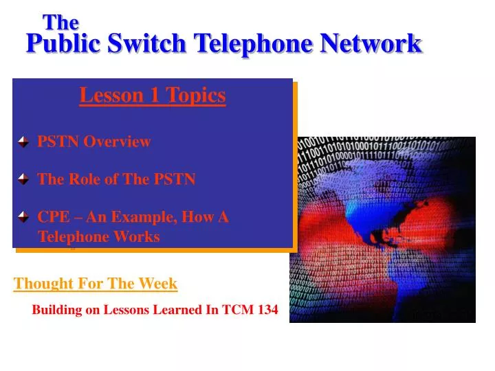
The. Public Switch Telephone Network. Lesson 1 Topics PSTN Overview The Role of The PSTN CPE – An Example, How A Telephone Works. Thought For The Week Building on Lessons Learned In TCM 134. STUDY GUIDE. Study This Set Of PowerPoint Slides

E N D
The Public Switch Telephone Network • Lesson 1 Topics • PSTN Overview • The Role of The PSTN • CPE – An Example, How A • Telephone Works Thought For The Week Building on Lessons Learned In TCM 134
STUDY GUIDE • Study This Set Of PowerPoint Slides • Complete Assignment 1 And Post All Answers • In The Lesson 1 Drop Box By The Due Date.
Objectives • In This Lesson, You Will Learn How The Public • Switch Telephone Network (PSTN) Was • Originally Designed To Carry Voice Services. • Next, We Will Learn That The Original Design • Of The PSTN Has Evolved To Carry Most Of • Today’s Advanced Voice, Data And Video • Services. • You Will Study A Brief Overview Of The PSTN – • A Building Block For Our Course. • Finally, You Will Learn How One Piece Of CPE • Works In Conjunction With The PSTN.
What Is The PSTN? • The Public Switch Telephone Network (PSTN) • Is A Mesh Network Of Lines, Trunks, Switches, • Etc. That Connects Customer Provided • Equipment (CPE) Together To Allow The CPE To • Communicate Together. • The PSTN Was Originally Designed To Optimize • The Transmission Of Voice Services.
Major Elements Of The PSTN CO Class 1 Switch PSTN CO Class 2 Switch Digital Interoffice Trunks CO Class 5 Switch Analog Loop Digital Loop PBX or KTS Residence CPE Office Bldg
The Four Major Elements Of The PSTN • There Are Four Major Elements Of Today’s Public • Switched Telephone Network (PSTN). • Customer Premises Equipment (CPE) • Access System • Transport • Signaling
Customer Premises Equipment • Prior To 1984 And The Breakup Of The AT&T Monopoly, • All Parts Of The Public Switched Telephone Network Was Owned And Operated By The Telephone Company. • After 1984, The Ownership And Maintenance Of All Telecommunications Equipment And Wiring On The Customer’s Site Became The Responsibility Of The Customer.
Customer Premises Equipment Includes: • Telephones • Fax Machines • Wiring & Jacks • Multiplexers • Cross Connect Systems • Computers • PBXs • Key Systems • CSUs • DSUs • Video Codecs • Etc.
Customer Premises Equipment - Continued: • Each Of These Pieces Of CPE Are Different. • They Each Work Differently Electronically, And Many • Have Different Ways In Which They Connect To The • PSTN. • Later In This Lesson We Will Study In More Detail, As • One CPE Example, How Telephones Work Electronically • And How They Connect To The PSTN. • Later In This Course, We Will Study How Several Other • CPEs Work Electronically And How They Connect To • The PSTN.
Demarcation Point • The FCC Defined A Point, The Demarcation Point, In The • Telecommunications Network That Separates CPE From • Telephone Company-Provided Equipment And Wiring. • The Demarcation PointIs Often Referred To As The Demarc.
Access System • The Access Component Of The PSTN Provides Customers • All Of The Wiring And Equipment For The Customer’s • CPE To Be Connected To The Central Core Of The Public • Switched Telephone Network. • The Access System Includes Both Lines And Trunks And The • Termination Equipment In The End Office. • Access Lines And Trunks Along With The Telephone Poles, • Conduits, Connector Boxes, Etc. Are Referred To As The • LocalLoop.
Central Office Termination Equipment • Some Samples Of End Office Termination Equipment.
Access System • Most Access Circuits Run From The Carrier’s Central Office • And A Residence Are Analog Circuits (Ref. Slide 6). • Most Access Circuits Run Between The Carrier’s Central • Central Office And Businesses With Private Branch • Exchanges Are Digital Circuits (Ref. Slide 6). • Since Most Circuits That Connect Central Offices To • Customer Premises Are Connected To Residences, Then, Most • Circuits In The Local Loop Are Analog.
Access System – Residential Access • Each Customer Circuit Is A Two-Wire Cable From The • Customer Demarc Out To The First Cross Connection Box Class 5 Switch • A & B – Cross • Connection Pedestal • Or Cross Connection • Box
Access System – Residential Access • Even Though Customer Circuits Are Two-Wire Cable, • Carriers Will Install Either 2-Pair, Or 4-Pair Cable. • Customer Circuits Are Combined With Other Circuits At The • Cross Connection Box Class 5 Switch 100-Pair Cable 2-Pair Cable
Access System – Residential Access Class 5 Switch • Each Customer Circuit Is A Two-Wire Cable From The • Customer Demarc Out To The First Cross Connection Box. • From The CrossConnection Box To The Central Office The • Customer Two-Wire Circuit Is Carried Inside Of A Much • Thicker Cable That Carries 100 Pairs Of Cable Or More. • Each Customer’s Two-Wire Circuits Remain Separate From • Other Customer’s Circuits Which Are Carried On Separate • Sets Of Wires.
Sample 4-Pair Cable • The Photo Below Shows A 4-Pair Copper Wire Cable • Similar To The Type Of Cable That Might Be Run To A • Residence. • Each Pair Of Cable Supports A Separate Circuit. • Because Of The Cost Of Installing Outside Cable, Carriers • Usually Install More Than 1 Pair Of Wires. Metal Conductor Plastic Insulator
Access System – Business Access Trunks Business W/ PBX Class 5 Switch • Access For Small Business Customer Circuits Are Similar To • Residential Access Circuits. • Business Trunks From PBXs Are Digital, Usually T1s Or T3s. • If The Trunks Are T1s, 24 Separate End-User Applications • Are Carried On One Set Of Wires At A Time. • We’ll Study More About Data Rates Of Trunks In The • Lessons In Module 3 Of Our Text.
Transport Component Of The PSTN • Transport Means Transmission – Taking Voice, Data, And • Video Signals From One Subscriber’s Access Line And • Delivering Them To Another Customer’s Access Line. • The End-Office, Or Class 5 Central Office Is The Point Where • All Customer Access Lines Connect. • The Trunks Within The Transport Core Include A Wide • Variety Of Transmission Speeds (e.g. T1, T3, OC-1, OC-12) • And Transmission Media (e.g. Copper And Optical Fiber). • We’ll Study More About The Transport System Later In This • Course.
Signaling Component Of The PSTN • Signaling Means The Controlling Of Calling Including: • Setting Up A Path For A Conversation Through The • Transport Core. • Maintaining And Terminating The Conversation Path. • Collecting Billing Information. • Handling Other Supervisory Functions. • We’ll Study More About The Signaling System Later In • This Course.
The Role Of The PSTN • Many People View Voice Services, And The PSTN • Used To Deliver Those Services, As “Old, Ho- Hum” • Topics. • Those People Reason That The Most Lucrative, • Future Growth Areas In Telecommunications Will • Be In Data Services As Opposed To Voice Services. • Many Of Those People Believe That • Telecommunications Students Should Not Study • Topics Related To Voice Communications Services • And The PSTN.
The Role Of The PSTN - Continued • Those Same People Believe That Data • Communications Will Underpin The New • Emerging Technologies And Will Be The “Wave • Of The Future”. Why Then Study Plain Old Telephony?
Throughout This Course We Will Learn How POTS And The PSTN Play Vital Roles In Providing Many Services Such As: • Voice-over-IP (VoIP) • Third Generation • Cellular • Internet Applications • E-Mail • E-Commerce • WANs & MANs • Etc., Etc., Etc. Today’s Emerging Technologies Do These Services Seem Like POTS!
Several Examples Of The Role Of The PSTN Cellular – Many Major Cellular Features Depend On The PSTN – Two Examples Follow
A Cell Call Placed To A Land-Based Phone Travels Through The PSTN CO Class 1 Switch Cellular User CO Class 2 Switch Digital Interoffice Trunks CO Class 5 Switch Radio Controller Analog Loop Residence CPE MTSO
Cellular Roaming Depends On The PSTN SS7 Network Roaming Cellular User STP STP SSP SS7/ PSTN SSP VLR HLR RoamingMTSO Home MTSO Cellular Roaming Would Not Be Possible Without SS7 Network In PSTN
Another Example Of The Role Of The • PSTN Private Line Data Networks Rely On Several Elements Of The PSTN
PSTN Backbone Circuits Are Provisioned To Create Corporate Private-Line Data Networks Site D Site A OC3 Private Line Router T3 Private Line Router 56 Kbps Private Line T1 Private Line Site E 56 Kbps Private Line Router Router 56 Kbps Private Line Site C Router Site B
ISP Access Use PSTN Circuits Corporate End-User CO Class 1 Switch PSTN CO Class 2 Switch Digital Interoffice Trunks MCDL CO Class 5 Switch Analog Loop Multiplexed/Channelized Digital Loop ISP Residential End-User Router
Customer Premises Equipment • CPE Includes All Telecommunications-Related Equipment That Is Located On The Consumer’s Side of the Demarcation Point. Customer Premises Equipment
Let’s Study How Telephones, One Type Of • CPE, Works Example Of Some Modern Telephones
DIRECT CURRENT • Do You Remember From TCM 134 How DC Current Flows? • Direct Current (DC) • - An Electrical Charge Flows Steadily In One Direction Over the Conductor. + Voltage - Time Voltage Over Time In A DC Circuit
Ohm’s Law: V = I x R I Flows When Switch Closed Resistor R Resistor R I DC Voltage DC Voltage DC Series Circuits With & W/O A Switch
Ohm’s Law: V = I x R • Do You Remember From TCM 134 How A Capacitor Affects • Current Flow In A Circuit? Capacitor Resistor R Capacitor Resistor R Does I Flow? Does I Flow? DC Voltage AC Voltage Does Current Flow In Circuits A Or B?
Functional Diagram – Telephone Set • Examine The Diagram Below To See If You Can Apply Any • Of The Lessons Learned From The Previous Two Slides. • Under What Conditions Will Current Flow (1) Through The • Ringer, (2) Through The Keypad, and (3) Into The Hybrid • Coil. Switch Hook T Receiver 1 2 3 Closed Line From CO 4 5 6 Ringer Hybrid Coil Balancing Network 7 8 9 * 0 # Transmitter R
What Does The Central Office Do To Allow You • To Dial Your Telephone? • What Should The CO Switch Do First? • What Should The CO Switch Do Next? Switch Hook T Receiver 1 2 3 Closed Line From CO 4 5 6 Ringer Hybrid Coil Balancing Network 7 8 9 * 0 # Transmitter R
How Does DTMF Dialing Work? • A Touch Tone Phone Operates By Transmitting A Combination Of Two Frequencies Each Time A Button Is Pressed. • Pressing Each Button Sends Out A Different Combination Of Frequencies.
How Does Rotary Dialing Work? • Rotary Dialing - A User Chooses A Number And Turns A Wheel From That Number To The Finger Stop Then Releases The Wheel. Finger Stop
How Does Rotary Dialing Work? - Continued • The Phone’s Internal Electronics Repeatedly • Breaks The Electric Current To Signal The • Number Dialed. • The Interrupts In The Current Causes Pulses Of • Specific Lengths, • These Pulses Of Interrupted Current Flow Are • Used In Pulse Dialing Rather Than Frequencies • To Represent Each Digit.
How Does Rotary Dialing Work? - Continued • To Dial The Number “2” The Phone’s • Electronics Breaks The Current 2 Times. • To Dial The Number “9” The Phone’s • Electronics Breaks The Current 9 Times. • Question: How Is The Number “0” Dialed?
Operation Of The Receiver And Transmitter • How Is Current Transitioned From The Two-Wire CO Circuit To • The Four Wires Required To Operate The Receiver And • Transmitter? • What Is An Impedance Mismatch & How Does It Apply Here? Switch Hook T Receiver 1 2 3 Closed Line From CO 4 5 6 Ringer Hybrid Coil Balancing Network 7 8 9 * 0 # Transmitter R
Carbon Filled Receiver/Transmitter • Carbon Particles Used To Create Current. • Transmitter - The Input Voice Alternately Compresses • The Carbon Particles Which Create A Matching • Oscillating Current. • Receiver – The AC Current • From The Telephone Wires • Moves A Membrane Which In • Turn Alternately Compresses • The Carbon Particles Which • Produces Sound.
Hybrid Coil And The Balancing Network • What Is The Role Of The Hybrid Coil Or Hybrid Network? • What Is The Role Of The Balancing Network? Switch Hook T Receiver 1 2 3 Closed Line From CO 4 5 6 Ringer Hybrid Coil Balancing Network 7 8 9 * 0 # Transmitter R
How Does The Central Office Ring Your • Telephone? • What Should The CO Switch Do First? • What Should The CO Switch Do Next? Switch Hook T Receiver 1 2 3 Open Line From CO 4 5 6 Ringer Hybrid Coil Balancing Network 7 8 9 * 0 # Transmitter R
Functional Diagram – Telephone Set: Switch • Hook Closed Current Switch Hook T Receiver 1 2 3 Closed Line From CO 4 5 6 Ringer Hybrid Coil Balancing Network 7 8 9 * 0 # Transmitter R Current • When The Switch Hook Is Closed, Current Flows.