Download
1 / 36
420 likes | 853 Vues
Public Switched Telephone Network (S-PSTN). S-PSTN.

E N D
S-PSTN • Partial support for this curriculum material was provided by the National Science Foundation's Course, Curriculum, and Laboratory Improvement Program under grant DUE-9972380 and Advanced Technological Education Program under grant DUE‑9950039. • GWEC EDUCATION PARTNERS: This material is subject to the legal License Agreement signed by your institution. Please refer to this License Agreement for restrictions of use.
Table of Contents Overview5 Learning Objectives6 Network Overview7 Switching Systems13 Post-Divestiture Network19 Signaling28 Contributors38
Overview • Network setup • Switching systems • Post-Divestiture network • Signaling • SS7 • CCS
Learning Objectives After completing this module you will be able to: • Discuss the basic operations of the Public Switched Telephone Network (PSTN) • Define the telephony switching hierarchy • Describe the signaling required to complete a typical telephone call through the PSTN • Describe how the SS7 network is overlayed onto the PSTN
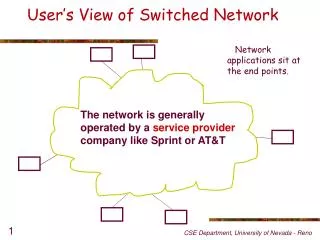
What Is A Network ? Switching Office Switching Office CPE CPE Transmission Facilities
Public Switched Telephone Network (PSTN) • Major Components of the Public Switched Telephone Network (PSTN): • Switching Offices • Transmission facilities • Customer Premise Equipment (CPE)
Switching Offices SWITCHING OFFICE CONTROL NETWORK
Transmission Facilities Switching Office Switching Office Trunks Line Line Special Service Circuit
Customer Premise Equipment (CPE) Customer Premise Equipment (CPE) is the term used to identify any piece of equipment supplied by the customer to interface with the PSTN. Examples include: • Single Line Telephone Set • Modems or Data Sets • Private Branch Exchange (PBX)
Traffic Networks • The Public Switched Telephone Network: • Pre-divestiture • Post-divestiture
Local Network Structure Exchange Area 2 Exchange Area 5 Exchange Area 1 Wire Center B • Wire Center A • Exchange Area 3 Exchange Area 4
Typical Local Network Tandem Office T Wire Center C Tandem Trunk Groups (Final) Wire Center A Wire Center B Direct Trunk Groups (High Usage)
FINAL Regional Center D Class 1 Regional Center E FINAL FINAL HU6 Regional Center C Class 2 Sectional Center F HU5 FINAL FINAL Primary Center G HU4 Regional Center B Class 3 HU7 HU2 HU3 FINAL FINAL HU1 Toll Center A Class 4 Toll Center H Toll Connecting Toll Connecting Toll Connecting Local Office (End Office) Class 5 Local Tandem Office Local Office Toll Network StructurePre-Divestiture Telephone 1 Telephone 2
FINAL Regional Center D Class 1 Regional Center E FINAL FINAL HU6 Regional Center C Class 2 Sectional Center F HU5 FINAL FINAL Primary Center G HU4 Regional Center B Class 3 HU7 HU2 HU3 FINAL FINAL HU1 Toll Center A Class 4 Toll Center H Toll Connecting Toll Connecting Toll Connecting Local Office (End Office) Class 5 Local Tandem Office Local Office Telephone 1 Telephone 2 Toll Network StructurePre-Divestiture
IEC1 IEC2 IEC3 LATA x InterLATA Carriers LATA y The Post-1984 Network
Typical LEC Network Central Office Tandem Office IC POP Switching Systems Distribution Facility/Local Loop Interoffice Facilities/Trunks Distribution Facility/Local Loop Central Office LEC IC
LATA Access Services • Switched Access • Special Access (Nonswitched)
Switched Access Service • Feature Group A • Feature Group B • Feature Group C • Feature Group D • Equal Access End Office
CentralOffice Numbering Plan Area Station N X X N X X X X X X 2-9 0-9 0-9 2-9 0-9 0-9 0-9 0-9 0-9 0-9 North American Numbering Plan
Number Plan Area (NPA) These special purposes codes include: NXX Reserved Codes: N11 Reserved Codes: 311 Non-Emergency Police and Fire 411 Local Directory Assistance 611 Repair Service* 811 Business Office* 911 Emergency Number 600 Used in Canada for TWX (teletype service) 700 Assigned to ICs 800, 888, 877, and 866 Service (INWATS) 900 Service (DIAL-IT Service)
160-8* = 152 *Excluding codes of N11 format 800-8* = 792* *Excluding codes of N11 format Old Format New format N 0/1 X 8 x 2 x 10 = 160 N X X 8 x 10 x 10 = 800 Number Plan Area (NPA) Interchangeable area (or NPA) codes are NPA codes of the format NXX. By changing from the former N-0/1-X format to the NXX format, the maximum number of assignable NPA codes increased by 640 codes as shown:
1, 2 or 3 digits Varies by location Country Codes Trunk Code Local Code Subscriber Number International Numbering If you have made international calls, you know that the familiar NANP is a subset of the ITU international plan. Until recently, international numbers were limited to 12 digits.
Signaling Signaling is the generation, transmission, and reception of information needed to direct and control the setup and disconnect of a call.
1 2 3 Signaling Terminating Switching Office Originating Switching Office Originating CPE Terminating CPE Idle Off-hook Dial Tone Dialed Digits Off-hook Off-hook (wink) On-hook (wink) Dialed Digits Ringing Audible Ring Answer Off-hook Disconnect
1 2 3 4 5 6 6 Signaling Terminating Switching Office Terminating Switching Office Originating Switching Office Originating CPE Terminating CPE Idle Off-hook Dial Tone Dialed Digits Off-hook Off-hook (wink) On-hook (wink) Dialed Digits Ringing Audible Ring Answer Off-hook Disconnect
1 2 3 4 5 6 6 7 8 Signaling Terminating Switching Office Terminating Switching Office Originating Switching Office Originating CPE Terminating CPE Idle Off-hook Dial Tone Dialed Digits Off-hook Off-hook (wink) On-hook (wink) Dialed Digits Ringing Audible Ring Answer Off-hook Disconnect
1 2 3 4 5 6 6 7 8 9 10 10 Signaling Terminating Switching Office Originating Switching Office Originating CPE Terminating CPE Idle Off-hook Dial Tone Dialed Digits Off-hook Off-hook (wink) On-hook (wink) Dialed Digits Ringing Audible Ring Answer Off-hook Disconnect
Common Channel Signaling (CCS) Common Channel Signaling (CCS) is a signaling method that uses a separate dedicated channel to send and receive signaling information for a group of trunks or facilities by means of labeled messages.
F E B B D Signaling System 7 (SS7) LINKS CO CO CO A A STP STP C STP STP C A A SCP SCP
Switching Office B Switching Office A STP Customer “B” Customer “A” IAM IAM ACM ACM ANM ANM REL REL RLC RLC SS7
Network Administration, Maintenance and Services • Network Management • Traffic Measurements • Billing • Maintenance • Customer Services