Download
1 / 41
750 likes | 1.59k Vues
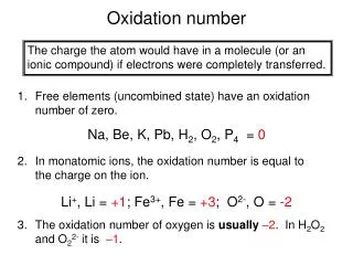
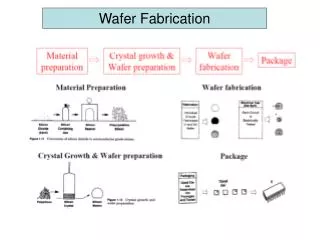
Epitaxy & oxidation (with wafer cleaning). sami.franssila@aalto.fi. Homoepitaxy: crystalline film A on top a crystalline wafer A. Single crystal wafer. Epitaxial layer of the same material deposited on top. CVD epitaxy of silicon. SiH 2 Cl 2 (g) ==> Si (s) + 2 HCl (g), T = 1150 o C

E N D
Epitaxy & oxidation(with wafer cleaning) sami.franssila@aalto.fi
Homoepitaxy: crystalline film A on top a crystalline wafer A Single crystal wafer Epitaxial layer of the same material deposited on top
CVD epitaxy of silicon SiH2Cl2 (g) ==> Si (s) + 2 HCl (g), T = 1150oC SiCl4 (g) + 2 H2 (g) <==> Si (s) + 4 HCl (g), T = 1250oC
Epitaxial or not ? Failed epitaxy: lattices do not match Successful epitaxy: the number of foreign atoms (e.g. arsenic dopants) is so small that the lattice structure beholds
Epi requirements Matching lattices Small enough CTE difference Clean surface
ox SEG Si ox ELO Si ox Selective epitaxy SEG: Selective Epitaxial Growth ELO: Epitaxial Lateral Overgrowth
Growth vs. etching SiH2Cl2 (g) ==> Si (s) + 2 HCl (g), SiCl4 (g) + Si (s) ==> 2 SiCl2 (g)
Rate At low temperature chemical surface reaction is slow, and there are plenty of source gas available. The process is surface reaction limited. At high temperatures reaction on surface is fast, and deposition rate is limited by supply of source gas by flow. Deposition is mass transport limited.
Epi vs. poly High rate results in polycrystalline material: the arriving atoms do not have enough time to find energetically favourable positions before the next layer of atoms arrive.
Transition width Boron doped epi, 1 µm nominal, SPR measured doping profile
Si 15 nm 10 nm 10 nm 10 nm 50 nm 10 nm 500 µm Si90Ge10 epi-layers Si85Ge15 Si wafer 500 µm b n- epilayer, 45 µm n+ epilayer, 6 µm p+ wafer, 300 µm a Layer thickness and interface abruptness Thin heteroepitaxial Si1-xGex layers for high speed bipolar transistors. The hatched layers are graded epi layers with constantly changing germanium content. Thick homoepitaxial silicon layers for IGBT power transistor;
Characterization • Visualinspection on all wafers. • Resistivity measurement from a test wafer using either a 4-point probe (n/P and p/N -structures) or CV (p/P and n/N). Destructive methods! • Thickness measurement optically with an FTIR from a p/P+ or n/N+ -structure. Nondestructive! • Transition width using SRP. • Automated inspection for particles, surface defects of allSSP wafers. • Other measurements as required.
Epi applications: electronics 1-2 µm P-type epi P- substrate CMOS: p-type epi on a P- substrate. Produces COP-free surface. Thickness and resistivity uniformity specifications not critical. Power devices: Highly doped substrate reduces resistive losses, but devices need to be made in lightly doped material.
n- epi p++ epi p-Si p-Si Epi applications: MEMS Membrane thickness control in MEMS: electrochemical etch stop P++ etch stop: when boron concentration exceeds 5*1019 cm-3, KOH etching slows down
Heteroepitaxy: crystalline film A on top a crystalline wafer B Multiple layers of single crystal AlAs and GaAs grown on top of single crystal GaAs wafer
Lattice match requirement Misfit = (a subs – a film)/a subs for Si & Ge, 4.17 % difficult Thermal expansion: for Si and GaAs 2.6 ppm/oC vs. 6.8 ppm/oC
Solar cell: 35 epi-layers Fig. 6.2: Superlattice structure of a quantum well solar cell with 30 periods of GaAs/InGaP, from ref. Magnanini
Active vs. passive cleaning • Cleanroom (and its subsystems) provide passive cleanliness • Wafer cleaning provides active cleaning
Wafer cleaning • removal of added contamination • ultrapure chemicals (very expensive) • particle-free (filtered 0.3 µm) • always includes rinsing & drying steps (with ultrapure water and nitrogen)
Surface preparation • leaves wafer in known surface condition • eliminates previous step peculiarities • eliminates waiting time effects • Wafer cleaning is the same as surface preparation; it is just a different viewpoint of wafer cleanliness
Contact angle θ Ultrahydrophilic (θ ~ 10o) Hydrophilic (θ ~ 70o) Hydrophobic (θ >90o) If surface is hydrophobic, water-based cleaning chemicals will be ineffective
RCA-1 • NH4OH:H2O2:H2O (1:1:5) ammonia-peroxide mixture • operated at 80oC • removes particles • removes organic (polymeric) materials • leaves surface hydrophilic
RCA-2 • HCl:H2O2:H2O (1:1:6) • hydrogen chloride-peroxide mixture • operated at 80oC • removes metal contamination • leaves surface hydrophilic
Sulphuric acid • H2SO4 is a strong oxidant • oxidizing effect is enhanced by addition of peroxide H2O2 • 120oC operating temperature • strong burn effects if spilled on humans • flush with safety shower immediately
HF • hydrofluoric acid • removes SiO2 • comes in many varieties: • DHF (dilute HF) HF:H2O (1:100-1000) (room temp) • BHF (buffered HF) (ca. 10%) (at 35oC) • strong HF (49%) (room temperature) • leaves surface hydrophobic • does not give a burning sensation immediately • delayed attack on bone after diffusing through the skin • special gel for treatment !
oxygen hydrogen nitrogen DCE/HCl burn box 3-zone resistive heating Thermal oxidation (at ~1000oC) Wet oxidation: Si (s) + 2 H2O (g) ==> SiO2 (s) + 2 H2 (g) Dry oxidation: Si (s) + O2 (g) ==> SiO2 (s)
Thermal oxide vs. CVD oxide O2 gas in thermal, 1000oC Compressive stress always, silicon consumed silicon SiH4 + N2O gases in Stress can be tailored tensile or compressive, deposition also on metals any wafer CVD 300-900oC
Masked oxidation • Nitride prevents oxide diffusion oxidation areas defined by nitride lithography & etching
Uses of oxide • etch mask material in KOH and TMAH silicon etching • diffusion mask in boron/phosphorous doping • electrical insulator • thermal insulator • hydrophilic surface • sacrificial material to be etched away
Oxide membrane • 1. KOH etched trench, mask oxide etched away (from both sides) • 2. Thermal oxidation (both sides of the wafer) • 3. Lithography on back, oxide etching from back, strip resist • 4. KOH etching back side, stops at oxide • 5. Thermal oxidation, both sides oxidized • top & bottom oxide thicker (NOTE: oxide penetrates into silicon) • central oxide thickness unchanged (no silicon available)
Sharp oxide tips Thermal oxide mask Further thermal Wet etching all oxide Isotropic silicon etch oxidation in HF Why not isotropic etching with resist mask ?
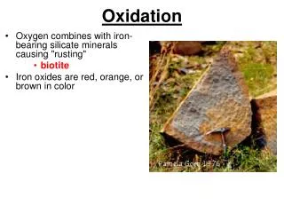
What happens to materials in oxygen at 1000oC ? -silicon -epitaxial silicon -polysilicon -amorphous silicon oxidized into SiO2 -silicon nitride: not affected -metals: melted (Al m.p. 653C) and oxidized -metals: oxidized (e.g. CuO) (==> not conductive any more) -metals: reacted with silicon (e.g. TiSi2 , conductor) -polymers (e.g. resist): burned (CO2; H2O)