Download
1 / 40

E N D
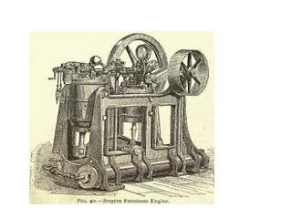
Brayton Cycle The Brayton cycle is the air-standard ideal cycle approximation for the gas-turbine engine. This cycle differs from the Otto and Diesel cycles in that the processes making the cycle occur in open systems or control volumes. Therefore, an open system, steady-flow analysis is used to determine the heat transfer and work for the cycle. We assume the working fluid is air and the specific heats are constant and will consider the cold-air-standard cycle.
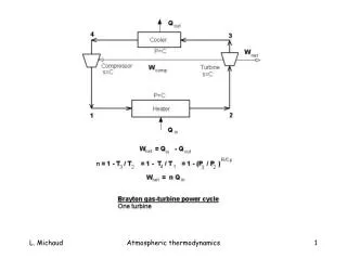
Process Description 1-2 Isentropic compression (in a compressor) 2-3 Constant pressure heat addition 3-4 Isentropic expansion (in a turbine) 4-1 Constant pressure heat rejection The T-s and P-v diagrams are
Thermal efficiency of the Brayton cycle Now to find Qin and Qout. Apply the conservation of energy to process 2-3 for P = constant (no work), steady-flow, and neglect changes in kinetic and potential energies. The conservation of mass gives For constant specific heats, the heat added per unit mass flow is
The conservation of energy for process 4-1 yields for constant specific heats (let’s take a minute for you to get the following result) The thermal efficiency becomes
Recall processes 1-2 and 3-4 are isentropic, so Since P3 = P2 and P4 = P1, we see that The Brayton cycle efficiency becomes Is this the same as the Carnot cycle efficiency? Since process 1-2 is isentropic,
where the pressure ratio is rp = P2/P1 and Extra Assignment Evaluate the Brayton cycle efficiency by determining the net work directly from the turbine work and the compressor work. Compare your result with the above expression. Note that this approach does not require the closed cycle assumption.
Example 9-2 The ideal air-standard Brayton cycle operates with air entering the compressor at 95 kPa, 22oC. The pressure ratio rp is 6:1 and the air leaves the heat addition process at 1100 K. Determine the compressor work and the turbine work per unit mass flow, the cycle efficiency, the back work ratio, and compare the compressor exit temperature to the turbine exit temperature. Assume constant properties. Apply the conservation of energy for steady-flow and neglect changes in kinetic and potential energies to process 1-2 for the compressor. Note that the compressor is isentropic. The conservation of mass gives
For constant specific heats, the compressor work per unit mass flow is Since the compressor is isentropic
The conservation of energy for the turbine, process 3-4, yields for constant specific heats (let’s take a minute for you to get the following result) Since process 3-4 is isentropic
Since P3 = P2 and P4 = P1, we see that We have already shown the heat supplied to the cycle per unit mass flow in process 2-3 is
The net work done by the cycle is The cycle efficiency becomes
The back work ratio is defined as Note that T4 = 659.1 K > T2 = 492.5 K, or the turbine outlet temperature is greater than the compressor exit temperature. Can this result be used to improve the cycle efficiency? What happens to th, win /wout, and wnet as the pressure ratio rp is increased? Consider the T-s diagram for the cycle and note that the area enclosed by the cycle is the net heat added to the cycle. By the first law applied to the cycle, the net heat added to the cycle is equal to the net work done by the cycle. Thus, the area enclosed by the cycle on the T-s diagram also represents the net work done by the cycle.
Let's take a closer look at the effect of the pressure ratio on the net work done.
Note that the net work is zero when For fixed T3 and T1, the pressure ratio that makes the work a maximum is obtained from: This is easier to do if we let X = rp(k-1)/k Solving for X
Then, the rp that makes the work a maximum for the constant property case and fixed T3 and T1 is • For the ideal Brayton cycle, show that the following results are true. • When rp = rp, max work, T4 = T2 • When rp < rp, max work, T4 > T2 • When rp > rp, max work, T4 < T2 The following is a plot of net work per unit mass and the efficiency for the above example as a function of the pressure ratio.
Regenerative Brayton Cycle For the Brayton cycle, the turbine exhaust temperature is greater than the compressor exit temperature. Therefore, a heat exchanger can be placed between the hot gases leaving the turbine and the cooler gases leaving the compressor. This heat exchanger is called a regenerator or recuperator. The sketch of the regenerative Brayton cycle is shown below.
We define the regenerator effectiveness regen as the ratio of the heat transferred to the compressor gases in the regenerator to the maximum possible heat transfer to the compressor gases.
For ideal gases using the cold-air-standard assumption with constant specific heats, the regenerator effectiveness becomes Using the closed cycle analysis and treating the heat addition and heat rejection as steady-flow processes, the regenerative cycle thermal efficiency is Notice that the heat transfer occurring within the regenerator is not included in the efficiency calculation because this energy is not heat transferred across the cycle boundary. Assuming an ideal regenerator regen = 1 and constant specific heats, the thermal efficiency becomes (take the time to show this on your own)
When does the efficiency of the air-standard Brayton cycle equal the efficiency of the air-standard regenerative Brayton cycle? If we set th,Brayton = th,regen then Recall that this is the pressure ratio that maximizes the net work for the simple Brayton cycle and makes T4 = T2. What happens if the regenerative Brayton cycle operates at a pressure ratio larger than this value?
For fixed T3 and T1, pressure ratios greater than this value cause T4 to be less than T2, and the regenerator is not effective. What happens to the net work when a regenerator is added? What happens to the heat supplied when a regenerator is added? The following shows a plot of the regenerative Brayton cycle efficiency as a function of the pressure ratio and minimum to maximum temperature ratio, T1/T3.
Example 9-3: Regenerative Brayton Cycle Air enters the compressor of a regenerative gas-turbine engine at 100 kPa and 300 K and is compressed to 800 kPa. The regenerator has an effectiveness of 65 percent, and the air enters the turbine at 1200 K. For a compressor efficiency of 75 percent and a turbine efficiency of 86 percent, determine (a) The heat transfer in the regenerator. (b) The back work ratio. (c) The cycle thermal efficiency. Compare the results for the above cycle with the ones listed below that have the same common data as required. The actual cycles are those for which the turbine and compressor isentropic efficiencies are less than one. (a) The actual cycle with no regeneration, = 0. (b) The actual cycle with ideal regeneration, = 1.0. (c) The ideal cycle with regeneration, = 0.65. (d) The ideal cycle with no regeneration, = 0. (e) The ideal cycle with ideal regeneration, = 1.0. We assume air is an ideal gas with constant specific heats, that is, we use the cold-air-standard assumption.
The cycle schematic is the same as above and the T-s diagram showing the effects of compressor and turbine efficiencies is below.
Compressor analysis The isentropic temperature at compressor exit is To find the actual temperature at compressor exit, T2a, we apply the compressor efficiency
Since the compressor is adiabatic and has steady-flow Turbine analysis The conservation of energy for the turbine, process 3-4, yields for constant specific heats (let’s take a minute for you to get the following result)
Since P3 = P2 and P4 = P1, we can find the isentropic temperature at the turbine exit. To find the actual temperature at turbine exit, T4a, we apply the turbine efficiency.
The turbine work becomes The back work ratio is defined as
Regenerator analysis To find T5, we apply the regenerator effectiveness.
To find the heat transferred from the turbine exhaust gas to the compressor exit gas, apply the steady-flow conservation of energy to the compressor gas side of the regenerator.
Using qregen, we can determine the turbine exhaust gas temperature at the regenerator exit.
Heat supplied to cycle Apply the steady-flow conservation of energy to the heat exchanger for process 5-3. We obtain a result similar to that for the simple Brayton cycle. Cycle thermal efficiency The net work done by the cycle is
The cycle efficiency becomes You are encouraged to complete the calculations for the other values found in the summary table.
Other Ways to Improve Brayton Cycle Performance Intercooling and reheating are two important ways to improve the performance of the Brayton cycle with regeneration.
P v The T-s diagram for this cycle is shown below. Sketch the P-v diagram.
0 Intercooling When using multistage compression, cooling the working fluid between the stages will reduce the amount of compressor work required. The compressor work is reduced because cooling the working fluid reduces the average specific volume of the fluid and thus reduces the amount of work on the fluid to achieve the given pressure rise. To determine the intermediate pressure at which intercooling should take place to minimize the compressor work, we follow the approach shown in Chapter 7. For the adiabatic, steady-flow compression process, the work input to the compressor per unit mass is
For the isentropic compression process Notice that the fraction kR/(k-1) = Cp. Can you obtain this relation another way? Hint: apply the first law to processes 1-4.
For two-stage compression, let’s assume that intercooling takes place at constant pressure and the gases can be cooled to the inlet temperature for the compressor, such that P3 = P2 and T3 = T1. The total work supplied to the compressor becomes To find the unknown pressure P2 that gives the minimum work input for fixed compressor inlet conditions T1, P1, and exit pressure P4, we set
This yields or, the pressure ratios across the two compressors are equal. Intercooling is almost always used with regeneration. During intercooling the compressor final exit temperature is reduced; therefore, more heat must be supplied in the heat addition process to achieve the maximum temperature of the cycle. Regeneration can make up part of the required heat transfer. To supply only compressed air, using intercooling requires less work input. The next time you go to a home supply store where air compressors are sold, check the larger air compressors to see if intercooling is used. For the larger air compressors, the compressors are made of two piston-cylinder chambers. The intercooling heat exchanger is often a pipe with a attached fins that connects the large piston-cylinder chamber with the smaller piston-cylinder chamber. Sometimes the fly wheel used to drive the compressor has fan type blades a spokes to increase air flow across the compressor and heat exchanger pipe to improve the intercooling effect.
Extra Assignment Obtain the expression for the compressor total work by applying conservation of energy directly to the low- and high-pressure compressors. Reheating When using multistage expansion through two or more turbines, reheating between stages will increase the net work done (it also increases the required heat input). The regenerative Brayton cycle with reheating was shown above. The optimum intermediate pressure for reheating is the one that maximizes the turbine work. Following the development given above for intercooling and assuming reheating to the high-pressure turbine inlet temperature in a constant pressure steady-flow process, we can show the optimum reheat pressure to be or the pressure ratios across the two turbines are equal.


![Tricarboxylic acid cycle (TCA Cycle) [Kreb’s cycle] [Citric acid cycle]](https://cdn2.slideserve.com/5062555/tricarboxylic-acid-cycle-tca-cycle-kreb-s-cycle-citric-acid-cycle-dt.jpg)