Download
1 / 24
240 likes | 366 Vues
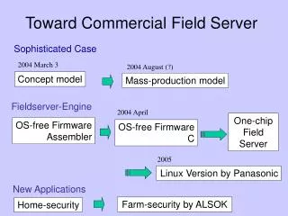
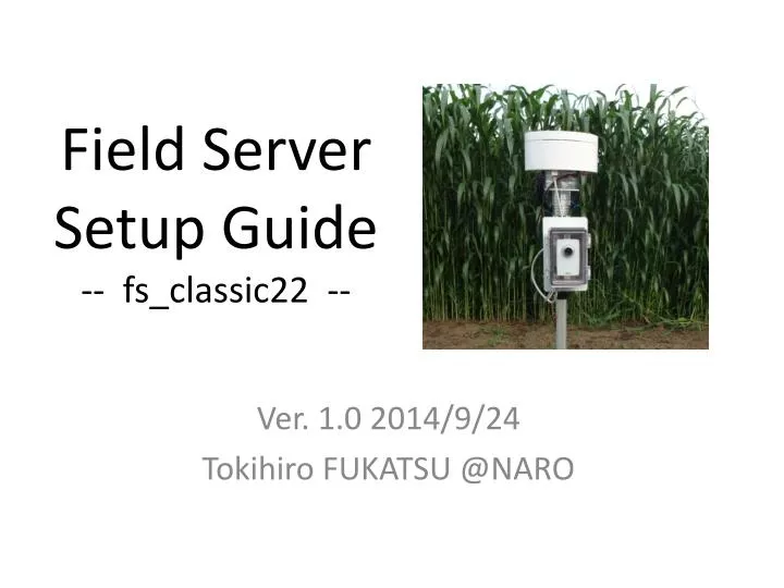
Field Server Setup Guide -- fs_classic22 --. Ver. 1.0 2014/9/24 Tokihiro FUKATSU @NARO. Contents. B. C. D. G. F. A. E. Part names and Functions. Main cover screw. indicator. sensor port. Mode selection switch. LAN port (12V PoE ). Power socket (In: 12V). LAN port.

E N D
Field Server Setup Guide-- fs_classic22 -- Ver. 1.0 2014/9/24 Tokihiro FUKATSU @NARO
Contents B C D G F A E
Part names and Functions Main cover screw indicator sensor port Mode selection switch LAN port (12V PoE) Power socket(In: 12V) LAN port
Part names and Functions Sleeve AD3 port AD2 port Air temperature & Humidity sensors Slide down
Preparation USB cable (A-B type) Wi-Fi router PC Phillips screwdriver
Setup (PC IP address) ① ② ④ ③
Setup (change camera IP address) Set your IP address Select these items
Setup (change Wi-Fi module setting) ② ③ ① ④ ⑤
Setup (change Wi-Fi module setting) ① ⑤ ④ ⑥ ② ③ ⑦
FS main program flowchart(setup) 12V in NTP access Push red button NTP failed NTP success D1: on D1: on D1: on D1: off D2: on D2: off Tweet FAN start Sleep Test mode Wait for wireless Main loop
FS main program flowchart(main_loop) Main loop Camera on FAN start Web server on Test mode Wait for wireless Check time Test mode monitor Sleep Tweet Main loop
Operate FS in test mode ・ Connect camera and FS PoE port ・ Check Wi-Fi hotspot is available ・ Plug the power holding red button ・ check D1/D2 on and then D1 off ・ access FS/camera web pages ・ check twitter data (twilog data) ・ reboot FS as a normal mode
FS Main web page Elapsed time Sensor RAW data (0-1023) CPU temp. = ad0/1024*100 (C) battery = ad1/1024*16 (V) Air temp. = ad2*0.108-8.2(C) Humid. = ad3*0.086+14(%RH) Raw data = ad4・ad5/1024(V) Control camera power Control FAN power If success tweet, indicate 200
FS main board 5V out 12V out Main 12V in FAN power Mode switch ad2 ad3 ad4 ad5 PoE power
FS main board parts list 4 14 9 1 11 15 12 9 5,6,7,8 2 3 13 10
Camera module with tripod tripod
Collect data by “Agent System” User Field Server Internet Agent System XML Parameter file Web application Web page Database Agent system automatically collect & display data