Download
1 / 14
140 likes | 293 Vues
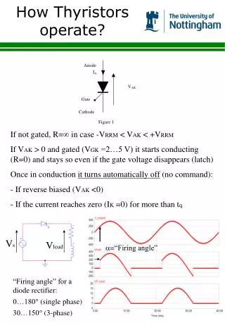
How Motors Operate Presented by John Freeland. Reference: Audel Electric Motors By Rex Miller & Mark Miller 6 th Edition Midcontinent Library Call Number: 621.46 M617. Voltage. +. time. -. Direct Current (DC) e.g. Battery. V=A sin (360ft). A. 45. 1/60 sec. RMS 120 volt

E N D
How Motors OperatePresented by John Freeland Reference: Audel Electric Motors By Rex Miller & Mark Miller 6th Edition Midcontinent Library Call Number: 621.46 M617
Voltage + time - Direct Current (DC) e.g. Battery V=A sin (360ft) A 45 1/60 sec RMS 120 volt Average 0 volt Peak (A) 170 volt 120 240 360 Three Phase Alternating Current Series Connection Parallel Connection
Basic Motor Operation N S N S
DC Motors - General • The speed is directly proportional to voltage • The DC motors we see are usually in vehicles, toys and cordless tools • They are fractional horsepower motors • Reversible by reversing the supply voltage polarity
DC Motors • 1. Wound rotor (armature) and wound field coil • Lower efficiency because energy required to energize field coils • Relatively high maintenance because of brushes and commutator • Example: First generation cordless drills • Permanent magnet field motor • Has wound rotor (armature) with commutator and brushes • Example: Some newer cordless drills and car door lock motor • Permanent magnet rotor • Has a wound field with electronics • Advantages: More efficient • Lower maintenance • Longer battery life • Example: New brushless drill motors
Universal Motors • Universal motors can operate on AC or DC power • Has a wound field coil, wound rotor with brushes and a commutator • Speed is proportional to applied voltage • Series wound universal motor (field coils and armature connected in series): • Can operate up to 20,000 rpm • Has poor speed regulation with varying load • Needs feedback circuitry to regulate speed • Example: Vacuum cleaner, router • Parallel wound universal motor (field coils and armature connected in parallel): • Operates at lower rpm • Has good speed regulation with varying load
Single Phase AC Motors • One common type is a split phase induction motor • Example: Table saw, planer, jointer, drill press… • The split phase stator has two windings: starting (auxiliary) and running • The starting winding: • Provides starting torque • Is disconnected by a centrifugal switch between 2/3 and 3/4 of the synchronous speed. 15% of synchronous speed is usually sufficient to start the motor. • This switch is a reliability issue. On a quiet machine/motor you can usually hear the switch open as the motor starts up and close as the motor turns off • Is offset from the running winding ninety degrees for a two pole motor and forty-five degrees for a four pole motor. • Has fewer turns of smaller gauge wire. • Occupies the outer portion of the stator slots.
Single Phase AC Motors • The starting and running windings are connected in parallel. Their relative connection determines if the motor runs clockwise or counterclockwise • If both ends of the starting and running windings are accessible, the motor can be reversed • “Induction” in a split phase induction motor means a current and therefore a magnetic field is induced in the rotor by the stator magnetic field (transformer action.) • The rotor usually has aluminum cast into the rotor laminations which create one turn coils. This arrangement gives rise to calling the motor a squirrel cage motor. • The speed of a squirrel cage, split phase, induction motor is nearly constant with load and depends on the line frequency, number of poles and slip. • The starting torque is 1.5 to 2.0 times the full-load torque • The starting current is 6 to 8 times the full load current. • Capacitors may be connected in series with the starting and/or running windings to increase torque and reduce starting current. These capacitors are a reliability issue.
Single Phase AC Motors • Synchronous speed Ns = RPM = 120 x frequency (f) = 7200 number of poles (p) (p)
Single Phase Motors • Slip is usually 1-4%of the synchronous speed and can be expressed three ways: • As a percent of synchronous speed • As a decimal fraction of synchronous speed • Directly in RPM
Three Phase AC Motors • Three phase power is “industrial power.” • Three phase power is how power is generated and distributed from the power plants • Three phase motors are very reliable because they don’t use brushes, a commutator, a starting centrifugal switch or a starting capacitor • Motor speed is a function of the number of poles, the line frequency and slip • Reversible by swapping any two of the three phase supply wires ABCABCABCABCABC CBACBACBACBACBA • Relatively inexpensive solid state controls are available to convert single phase power to three phase power with variable frequency and voltage (speed controls)
VFD Variable Frequency Drive • Refer to www.VFDs.com • A VFD is a motor controller that drives a motor by varying the frequency and voltage supply • Voltage to frequency ratio (V/F) remains constant from the VFD • The strength of the motor’s magnetic poles is proportional to V/F. If the ratio is too low the magnetic pole strength is too weak to create sufficient torque. If the ratio is too high the iron in the poles will magnetically saturate and cause overheating. • Maximum motor speed is 120% of rated speed • Minimum speed is 20% of maximum rated speed • Motor bearings have a higher failure rate when the motor is powered by a VFD