Download
1 / 22
220 likes | 360 Vues
Background effect to Vertex Detector and Impact parameter resolution. T. Fujikawa(Tohoku Univ.) Feb. 4 2005 LC Detector Meeting. Purpose. Goal: estimate the vertex detector performance. Step:. background study. impact parameter resolution. Tracking efficiency, b-tag and c-tag efficiency.

E N D
Background effect to Vertex Detector and Impact parameter resolution T. Fujikawa(Tohoku Univ.) Feb. 4 2005 LC Detector Meeting
Purpose Goal: estimate the vertex detector performance Step: background study impact parameter resolution Tracking efficiency, b-tag and c-tag efficiency
Pair background hit rate study Simulation tools • CAIN (for e+e- pair background (dominant) generation) Monte-Carlo program for the beam-beam interaction. (by Yokoya-san) Included interactions are… ・Jupiter (for pair background hit rate estimation) JLC Uniform Particle Interaction and Tracking EmulatoR. GEANT4 based full simulator for ILC (under construction…)
Beam parameters (for the CAIN) Beam parameters are mostly the same as the TESLA TDR. In order to obtain the high luminosity, beam focus is set in 250 micron in front of IP, and crab angle is included. IP = focus
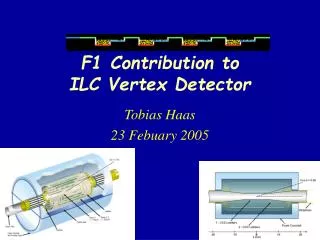
Detector configuration (for the Jupiter) Detector is constructed with the Beam pipe, Vertex detector (Ladder construction), Intermediate tracker, Mask, etc. and base geometry is “Old” one. (Namely, designed for “Warm” machine.)
The configuration of the vertex detector These conditions are applied to estimate pair background hit rate as first layer radius is varied.
polyethylene tungsten QC1 8.0cm 7.3cm 3.5cm 197.3cm 324.5cm L*=350cm 149.9cm 334cm The configuration of the forward region Al(thickness=2mm)
B = 3tesla, R1 = 1.2cm. Phi vs. Z Z Pair background hit rate for the vertex detector 1.hit point uniformity (for 1st. layer) We can use the average hit rate to estimate the occupancy.
Pair background hit rate for the vertex detector 2. Number of fired pixels per track hit (for 1st. layer) Number of fired pixels per 1 track passage is about 3.7. (independent of radius and B field) Number of fired pixel per track hit
20 readouts per train • 3.7 fired pixels per track hit • Pixel occupancy(%) = hit rate (/bunch/cm2) 0.326 • Set the first layer radius such that its pixel occupancy = 0.5% Pair background hit rate for the vertex detector 3. Determination of first layer radius
3 tesla 4 tesla 5 tesla First layer hit rate vs. first layer radius fit function: 0.5 % occupancy occurs at
Impact parameter resolutions 1. TRACKERR Estimates the impact parameter resolutions and momentum resolutions using TRACKERR. (assume pion). TRACKERR: FORTRAN program to calculate tracking error matrix with using cylindrically symmetric system. Energy loss, energy loss fluctuation and multiple scattering effects are included. Track fitting uses Kalman filter.
Detector configurations for TRACKERR 3 tesla 4 tesla 5 tesla Beam pipe (Be) VTX detector (Si pixel) IT (Si strip) TPC
Impact parameter resolutions of the r-phi plane Impact parameter resolutions are mostly the same for each magnetic field case. (true for other configurations with different thickness for BP and VTX detector.)
Impact parameter resolutions of the r-phi plane Other configuration results are as follows (at polar angle = 90 deg.): For P = 1GeV/c 3tesla is worse than 4(5) tesla by 12.0(19.2) %. For P = 10GeV/c 3tesla is worse than 4(5) tesla by 6.4(8.8) %.
Momentum resolutions Momentum resolution is better for high B at low P, and better for low B at high P.
Momentum resolutions Other configuration results are as follows (at polar angle = 90 deg.): Momentum resolution is better for high B at low P, and better for low B at high P.
the present condition: • tracking is performed by track ID • the material can be included as “uniform” one to calculate the error. (TPC-like) • cylindrical layer Impact parameter resolutions 2. Satellites (not finished…) Satellites: JSF based tracking program for the Jupiter. (under construction…)
B field 3 tesla Beam pipe (Be) VTX detector(Si) IT (Si) TPC Impact parameter resolutions Detector configuration for the Jupiter and Satellites
Impact parameter resolutions ref. results by TRACKERR (pion, cosq=0.1)
P=10GeV/c dr(mm) P=100GeV/c dr(mm) Impact parameter resolutions results by Satellites (pion, cosq=0.1) As mentioned above, results are little doubtful…
Next Plan • estimate the impact parameter resolutions using Satellites • estimate the b-tag, c-tag efficiency (with pair background) To do… • include thin layer construction (already implemented by Yamaguchi-san?) • make a track finder • include the (pair) backgroundhits in Satellites • other detector configurations (FPCCD etc.)