Download
1 / 7
70 likes | 133 Vues
Impact parameter resolution for different B fields. Tohoku Univ. T. Fujikawa. Last time:. Hit rate estimations of the pair background are finished….

E N D
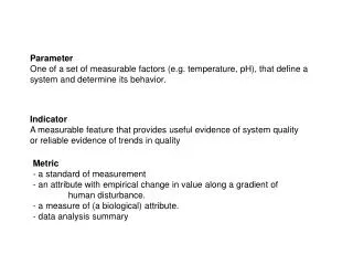
Impact parameter resolution for different B fields Tohoku Univ. T. Fujikawa
Last time: Hit rate estimations of the pair background are finished… I need to estimate the track error (impact parameter resolution) with using desirable detector configurations for each magnetic fields. (This results will be used for a comparative object of simulator results.)
Hit rate estimation Occupancy = 0.5% Occupancy = 0.5% Occupancy = 0.5% Occupancy = 0. 2% Occupancy = 0. 2% Occupancy = 0. 2% (transverse axis represents VTX detector Layer1 radii) According to this results… 3tesla : R1 = 1.7cm 4tesla : R1 = 1.45cm 5tesla : R1 = 1.3cm are desirable (if we allow 0.5% pair b.g. occupancy).
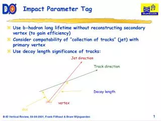
1. Analytical results (for charged π) dip angle = 0° dip angle = 30° (cf. GLC road map) Innermost 2-Layers are used to estimate impact parameter resolution. Last 2 terms represent multiple scattering effect of layer1 and beam pipe. (σ1,2 are assigned to be 2 micron) dip angle = 45° dip angle = 60° each plots have different dip angles (dip angle = π/2 - θ)
2. Results by using TRACKERR TRACKERR : FORTRAN program to calculate tracking error matrix with using cylindrically symmetric system. Energy loss, energy loss fluctuation and multiple scattering effects are included. The main limitation is that the trajectory is not modified by energy loss.
results of the TRACKERR calculation are… Detector configuration is… ・VTX detector & IT are included ・ distance between each layers of the VTX detector is 1.2cm, and Rbp = R1 –0.4cm. ・the geometry of IT is same as shown in the GLC road map. dip angle = 0° dip angle = 30° dip angle = 45° dip angle = 60° Impact parameter resolution in the x-y plane
Summary and Plan Track error (impact parameter resolution) estimations by using mathematical calculation are finished. Next step: to upgrade the Satellites (event reconstruction program which is related to Jupiter) and doing same estimation (and more) by using full simulator.