Download
1 / 36
450 likes | 761 Vues
Programmable System-on-Chip (PSoC) General Overview Embedded Architectures EE446. Typical Microcontroller Purposes. Computer. uC. Thermal. Gyro. Acceleration. The purpose for uC’s is to interface multiple types of hardware. Digital Input/Outputs: Switches Relays LEDs

E N D
Programmable System-on-Chip (PSoC) General OverviewEmbedded ArchitecturesEE446
Typical Microcontroller Purposes Computer uC Thermal Gyro Acceleration • The purpose for uC’s is to interface multiple types of hardware. • Digital Input/Outputs: • Switches • Relays • LEDs • Digital Communications: I2C, SPI • Analog Input/Outputs
Regular Microcontroller Caveats • What if you need more Analog Inputs? • What if you need more Interrupts? • Advanced projects: more PWMs needed? • Use external circuitry • Buy a larger microcontroller
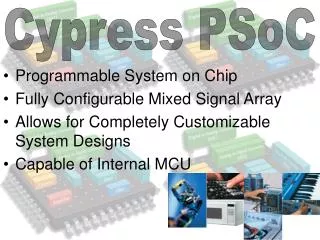
What is a Programmable System-on-Chip (PSoC)? • A customizable microcontroller that includes flexible analog and digital logic blocks. • Analog blocks: • High-resolution inputs (up to 20-bit) • 4 Digital-to-Analog Converters • Digital logic blocks (UDBs): • A wide mix of digital peripherals can be implemented into a single chip. • Up to 4 voltage domains • Almost all pins can be flexible in terms of being digital or analog.
What is a Programmable System-on-Chip (PSoC)? • PSoC-5 (Powered by ARM Core) • Provides above features plus ARM processor benefits: • Up to 67Mhz • Flash: Up to 256kb • SRAM: Up to 65kb • Up to 70 I/O pins
API Cypress PSoC IDE
PSoC Main Program Code ISR Flag Main loop ISR Flag
Extensive Uses of UDBs • Examples of possible hardware configurations on a single (and largest) PSoC chip: • 12 UARTs or • 28 PWMs • For a normal microcontroller, this configuration is impossible without resorting to additional external hardware, such as: • Daisy-chain or bus-connected peripherals: • Microcontrollers • I2C/SPI-connected hardware for UART, PWM, etc.
PSoC Analog Routing • Analog Local Bus • 4 on left side, 4 on right side • Connects to analog resource blocks only • No access to GPIO’s • Analog Global Bus • Connects I/O to analog resource blocks on same side • Connects to GPIO on their respective quadrant • 8 routes on left side, 8 routes on right side • Analog Mux Bus • Connects the buses to the ‘outside’ world • Can connect to all GPIO’s and all analog resource blocks
PSoC Die Quadrants Analog Routing Global Bus
Why have interrupts? • An external event that needs immediate attention. • An ‘emergency’ switch • A long-running timer • PSoC-5 supports 16 system interrupts and 32 from peripherals. • Tail Chaining (Back-to-Back) • Late Arrival (Lower Higher) • Reprioritize Interrupts • Same Priority? • Fixed Function DMA UDB
Interrupts • Some modules that are used needs immediate attention in real time.
Polling vs Interrupting • Signals can happen too fast for the CPU to read or process!
Example PSoC ProjectFirmware Overview I/O Communications Inputs From Sensors Outputs To Devices
Raw Sensor Data Collection to the Host PC • Digital: • I2C used in Gyroscopes, Accelerometers, Magnetometers (IMU), and Temperature Sensor • UART from Sonar @ 9600bps (8N1) • For this particular usage, very inefficient. • Requires interrupts and additional code complexity. • Very slow data updates. • ADC Settings and Inputs: • 14-bits @ 70,000 Samples Per Second (currently) • Vcc = 5 Volt (Reference) • Raw value range: • 0v 5v • 0 16384
PSoC Data Output Servo Position Infrared Gyro X-Axis Gyro Y-Axis Gyro Z-Axis Sonar (analog) Raw ADC Values: 85 updates/sec over Serial UART @ 115200bps (8N1)