Download
1 / 40
410 likes | 505 Vues
FIGURE 14.1 Typical parking brake cable system showing the foot-operated parking brake lever and cable routing. FIGURE 14.2 A typical parking brake pedal assembly.

E N D
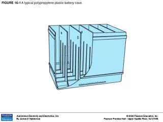
FIGURE 14.1 Typical parking brake cable system showing the foot-operated parking brake lever and cable routing.
FIGURE 14.3 Typical hand-operated parking brake. Note that the adjustment for the cable is underneath the vehicle at the equalizer.
FIGURE 14.4 A ratchet mechanism is used to lock parking brakes in the applied position.
FIGURE 14.6 Automatic parking brake release mechanisms usually use a vacuum servo to operate the release lever.
FIGURE 14.7 The two plastic vacuum tubes on the steering column are used to release the parking brake when the gear selector is moved from park into a drive gear.
FIGURE 14.8 The cable from the activating lever to the equalizer is commonly called the control cable.
FIGURE 14.9 Notice how rust inside the covering of this parking brake cable has caused the cable to swell.
FIGURE 14.10 Intermediate levers in the parking brake linkage increase the application force.
FIGURE 14.11 A cable guide is a common type of parking brake linkage equalizer.
FIGURE 14.12 Some parking brake equalizers are installed in the brake cable.
FIGURE 14.13 Many parking brake linkages use both an intermediate lever and an equalizer.
FIGURE 14.14 Notice the spring at the end of the parking brake strut. This antirattle spring keeps tension on the strut.
FIGURE 14.15 The parking brake cable pulls on the parking brake lever, which in turn forces the brake shoe against the drum.
FIGURE 14.16 The inside “hat” of the disc brake rotor is the friction surface for the parking brake shoes.
FIGURE 14.17 A typical rear disc brake auxiliary drum brake friction assembly.
FIGURE 14.18 A Ford rear brake caliper ball and ramp-type apply mechanism.
FIGURE 14.19 Operation of a ball and ramp-type rear disc brake caliper parking brake.
FIGURE 14.20 Automatic adjustment of a ball and ramp-type rear disc brake parking brake occurs when the service brakes are applied.
FIGURE 14.21 A typical General Motors rear disc brake with an integral parking brake. This type uses a screw, nut, and cone mechanism to apply the caliper piston.
FIGURE 14.22 Parking brake application of a General Motors rear drive brake caliper.
FIGURE 14.23 Automatic adjustment of a General Motors rear disc brake caliper.
FIGURE 14.24 Removing the piston from a typical General Motors rear disc brake caliper.
FIGURE 14.25 Installing the piston into a General Motors rear disc brake caliper.
FIGURE 14.26 A piston installation tool is often needed to complete the installation of the piston in a General Motors rear disc brake.
FIGURE 14.27 A spanner wrench (or needle-nose pliers) can be used to rotate the caliper piston prior to installing the disc brake pads.
FIGURE 14.28 After removing the parking brake lever and thrust bearing, remove the antirotation pin.
FIGURE 14.29 Unscrew the thrust screw from the piston with an Allen (hex) wrench. After removing the thrust screw, push the piston out of the caliper bore.
FIGURE 14.30 To test the piston adjuster, thread the thrust screw into the piston. Hold the piston and pull the thrust screw outward 1/4 inch (6 mm).
FIGURE 14.31 To adjust the parking brake cable on a Ford vehicle equipped with rear disc brakes, start by loosening the cable adjustment until the cables to the calipers are slack.
FIGURE 14.32 After checking that the rear brakes are okay and properly adjusted, the parking brake cable can be adjusted.
FIGURE 14.33 Many hand-operated parking brakes are adjusted inside the vehicle.
FIGURE 14.34 Always check that the brake shoes contact the anchor pin.
FIGURE 14.35 A 1/8 inch (3 mm) drill bit is placed through an access hole in the backing plate to adjust this General Motors leading-trailing rear parking brake.
FIGURE 14.36 Many parking brake cables can be removed easily from the backing plate using a 1/2 inch (13 mm) box-end wrench.
FIGURE 14.37 An electric parking brake button on the center console of a Jaguar.
FIGURE 14.38 A type of electric parking brake that uses an electric motor to pull on the parking brake cable to each rear wheel.
FIGURE 14.39 A scan tool can be used when servicing the rear brakes on a vehicle equipped with an electric parking brake.