Download
1 / 21
220 likes | 418 Vues
Micro-imaging Application of VCSELs. Group #11 Karthikraman Samakkulam, Neeta Acharya, Manan Shah. Outline. Project Motivation Advantages of VCSELs Challenges in Design Description of Design Problems Encountered Conclusion. Project Motivation. VCSEL used extensively in communications

E N D
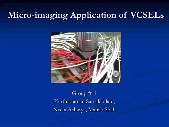
Micro-imaging Application of VCSELs Group #11 Karthikraman Samakkulam, Neeta Acharya, Manan Shah
Outline • Project Motivation • Advantages of VCSELs • Challenges in Design • Description of Design • Problems Encountered • Conclusion
Project Motivation • VCSEL used extensively in communications • Any other application? • Application in Micro Imaging • Projector Display • Bar Code Scanning
Benefits of VCSELs • Low divergence circular laser beam • High Resolution for Displays • Inexpensive as manufactured in bulk • Capability of manufacturing dense two dimensional laser arrays
Benefits of VCSELs • Low power Consumption • Durability • Operates at high frequencies (up to GHz) • Life 3-5 years
Description Of VCSEL • Structure of VCSELs Light out Contact DBR Oxide aperture DBR Contact
Challenges in Design • 64 VCSELs controlled independently • Different current ranges for each device Current at rollover = 27.84mA Threshold Current = 1.92mA
Challenges in Design • Insufficient I/O pins on Microcontroller • Extensive combinational logic required • Microcontroller with sufficient memory • Length of code in compliance with memory • Interface for visual display • High light intensity, damage to eyes
Project Design • Microcontroller : HC-12 Vs FPGA • Familiarity with VHDL • Sufficient available memory on FPGA • FPGA limitations • Only 23 I/O pins available • Converting 16 to 64
Circuit Design Function Generator clock FPGA 2:1 MUX 2:1 MUX MUX Select Groups of 4 VCSELs 74LS194 74LS195 Serial input Parallel Load
Circuit Design • 74LS194 (x16) • 4-Bit Bidirectional Universal Shift Register • Input received from FPGA • Shift Right performed on input bits • Output to 74LS195 • 74LS195 (x16) • 4-Bit Parallel Access Shift Register • Parallel load to outputs • Each 74LS195 controls 4 VCSELs
Circuit Design • 74LS157 (x2) • 2-to-1 Multiplexer • Select input to MUX controlled by FPGA • Select = ‘0’ : Outputs LOW • Select = ‘1’ : Outputs CLOCK • Resistors (x64) • Current limiting circuit • 910Ω
Design Test • 8 Single Packaged VCSELs • Logic test • Verify combinational logic • Checking for delays • Degradation of VCSELs
Before and After Voltage (V) Light Intensity (mW) Current (A)
Problems Encountered • Limitations in designing patterns • Size of VCSEL array • Wiring circuit • Magnification • 5X Lens
Problems Encountered • Keeping VCSEL array flat • Variations in brightness • Non-uniformity of fabrication process • Replaced 910Ω resistor with 470Ω
Conclusion • Successful implementation of 8 patterns • Code length : 90Kb • Memory usage : 63Mb • Frequency used : 8Hz • Voltage (peak-to-peak) : 3.5V • Gates used : 9572 out of 100,000
Recommendations for Future • Keyboard input • Changes in code implementation • Minimize the length of code • Using larger VCSEL arrays
Acknowledgements • Professor Choquette • Spencer Hoke