Download

1 / 18
180 likes | 456 Vues
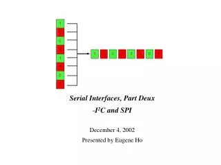
Serial Interfaces, Part Deux I 2 C and SPI December 4, 2002 Presented by Eugene Ho. Introduction. I 2 C and SPI Serial communication protocols Meant for short distances “inside the box” Low complexity Low cost Low speed ( a few Mbps at the fastest )

E N D
Serial Interfaces, Part Deux • I2C and SPI • December 4, 2002 • Presented by Eugene Ho
Introduction I2C and SPI • Serial communication protocols • Meant for short distances “inside the box” • Low complexity • Low cost • Low speed ( a few Mbps at the fastest ) • To be discussed: Applications, protocols, tradeoffs, AVR support
What is I2C? • Shorthand for an “Inter-integrated circuit” bus • Developed by Philips Semiconductor for TV sets in the 1980’s • I2C devices include EEPROMs, thermal sensors, and real-time clocks • Used as a control interface to signal processing devices that have separate data interfaces, e.g. RF tuners, video decoders and encoders, and audio processors. • I2C bus has three speeds: • Slow (under 100 Kbps) • Fast (400 Kbps) • High-speed (3.4 Mbps) – I2C v.2.0 • Limited to about 10 feet for moderate speeds
I2C Bus Configuration • 2-wire serial bus – Serial data (SDA) and Serial clock (SCL) • Half-duplex, synchronous, multi-master bus • No chip select or arbitration logic required • Lines pulled high via resistors, pulled down via open-drain drivers (wired-AND)
I2C Protocol 1. Master sends start condition (S) and controls the clock signal 2. Master sends a unique 7-bit slave device address 3. Master sends read/write bit (R/W) – 0 - slave receive, 1 - slave transmit 4. Receiver sends acknowledge bit (ACK) 5. Transmitter (slave or master) transmits 1 byte of data
I2C Protocol (cont.) 6. Receiver issues an ACK bit for the byte received 7. Repeat 5 and 6 if more bytes need to be transmitted. 8.a) For write transaction (master transmitting), master issues stop condition (P) after last byte of data. 8.b) For read transaction (master receiving), master does not acknowledge final byte, just issues stop condition (P) to tell the slave the transmission is done
I2C Signals • Start – high-to-low transition of the SDA line while SCL line is high • Stop – low-to-high transition of the SDA line while SCL line is high • Ack – receiver pulls SDA low while transmitter allows it to float high • Data – transition takes place while SCL is slow, valid while SCL is high
I2C Features • “Clock stretching” – when the slave (receiver) needs more time to process a bit, it can pull SCL low. The master waits until the slave has released SCL before sending the next bit. • “General call” broadcast – addresses every device on the bus • 10-bit extended addressing for new designs. 7-bit addresses all exhausted
AVR Support for I2C • Atmel calls it “Two-wire Serial Interface” (or TWI) • Supported by all AVR 8-bit μC except ATTiny and AT90 ATmega323 TWI mode when TWEN in TWCR is set: • PC0=SCL, PC1=SDA • TWBR – sets bit rate • TWCR – controls start, stop, ack generation, indicates M/S, T/R • TWDR – contains byte transmitted/received • TWAR – contains slave address • TWSR – indicates status of TWI Bus (start condition transmitted, ACK received, … 26 total states)
I2C Tradeoffs Advantages: • Good for communication with on-board devices that are accessed occasionally. • Easy to link multiple devices because of addressing scheme • Cost and complexity do not scale up with the number of devices Disadvantages: • The complexity of supporting software components can be higher than that of competing schemes ( for example, SPI ).
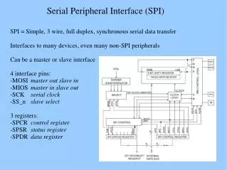
What is SPI? • Shorthand for “Serial Peripheral Interface” • Defined by Motorola on the MC68HCxx line of microcontrollers • Generally faster than I2C, capable of several Mbps Applications: • Like I2C, used in EEPROM, Flash, and real time clocks • Better suited for “data streams”, i.e. ADC converters • Full duplex capability, i.e. communication between a codec and digital signal processor
SPI Bus Configuration • Synchronous serial data link operating at full duplex • Master/slave relationship • 2 data signals: • MOSI – master data output, slave data input • MISO – master data input, slave data output • 2 control signals: • SCLK – clock • /SS – slave select (no addressing)
SPI vs. I2C • For point-to-point, SPI is simple and efficient • Less overhead than I2C due to lack of addressing, plus SPI is full duplex. • For multiple slaves, each slave needs separate slave select signal • More effort and more hardware than I2C
SPI Protocol • 2 Parameters, Clock Polarity (CPOL) and Clock Phase (CPHA), determine the active edge of the clock • Master and slave must agree on parameter pair values in order to communicate
SPI Protocol (cont.) • Hardware realization is usually done with a simple shift register • SPI interface defines only the communication lines and the clock edge • There is no specified flow control! No acknowledgement mechanism to confirm receipt of data
AVR Support for SPI • Supported by all AVR 8-bit μC except ATTiny and some AT90s ATmega323 - SPI mode when SPE bit in SPCR is set: • PB6=MISO, PB5=MOSI, PB7=SCK, PB4=/SS • SPCR – sets bit rate, CPOL, CPHA, M/S • SPDR – used for data transfer to and from SPI shift register • For multiple slaves, must employ “bit-banging”. Use software to control serial communication at general-purpose I/O pins.
Summary • I2C and SPI provide good support for communication with slow peripheral devices that are accessed intermittently, mainly EEPROMs and real-time clocks • I2C easily accommodates multiple devices on a single bus. • SPI is faster, but gets complicated when there is more than one slave involved.
References I2C: • http://www-us2.semiconductors.philips.com/acrobat/various/ I2C_BUS_SPECIFICATION_1995.pdf • http://www.esacademy.com/faq/i2c/index.htm • http://www.embedded.com/story/OEG20020528S0057 SPI: • MC68HC11 manual • http://www.mct.net/faq/spi.html • http://links.epanorama.net/links/serialbus.html • http://www.embedded.com/story/OEG20020124S0116