Download
1 / 27
280 likes | 495 Vues
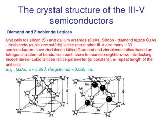
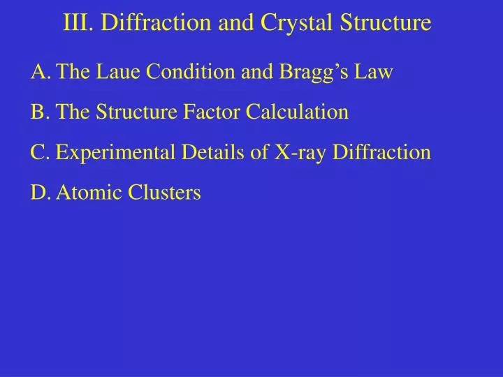
III. Diffraction and Crystal Structure. The Laue Condition and Bragg’s Law The Structure Factor Calculation Experimental Details of X-ray Diffraction Atomic Clusters.

E N D
III. Diffraction and Crystal Structure • The Laue Condition and Bragg’s Law • The Structure Factor Calculation • Experimental Details of X-ray Diffraction • Atomic Clusters
In a diffraction grating for visible light, constructive interference between light rays passing through slits of the grating leads to light intensity ONLY at certain locations on the screen: A. The Laue Condition and Bragg’s Law d n = 2 n = 1 n = 0 n = -1 n = -2 grating screen
Starting Assumptions For x-rays, electrons, and neutrons incident on a crystal, diffraction occurs due to interference between waves scattered elastically from the atoms in the crystal. If we treat the incident waves as plane waves and the atoms as ideal point scatterers, the scattered waves are spherical waves. We will assume they are also isotropic.
Physical Model for X-ray Scattering Consider two parallel plane waves scattered elastically from two nearby atoms A and B in a solid material: A P O B f = atomic form factor (scattering power of atom) elastic scattering:
Phase Difference Between the Waves For the spherical waves scattered from atoms A and B (of the same type): where: = position of detector relative to A = position of detector relative to B = position of B relative to A = phase difference between and scattering vector phase lag from O B phase advance from A P
Sum of Scattered Waves So the wave scattered from the jth atom is: = position of atom j relative to A Thus the total scattered wave at the detector is: For a small sample, the distances rj are all essentially the same ( R). Thus we see that constructive and destructive interference between the scattered waves that reach the detector is due to the atomic sum. The detector location is determined by the scattered wave vector and thus .
Summing Over All Atoms Now assume a crystal whose lattice has base vectors , with a total number of atoms along each axis M, N, and P, respectively: Thus the amplitude of the total wave at the detector is proportional to: which can be rearranged to give:
We need only evaluate the sum inside the brackets: Evaluating the Sum Now the intensity of the total wave at the detector is given by: which simplifies to give:
Now use the familiar identity: The Bottom Line which gives the result: This is the same as the intensity of an M-slit diffraction grating. If M is large ( 108 for a macroscopic crystal), it has very narrow, intense peaks where the denominator goes to zero. In between the peaks the intensity is essentially zero. Remembering that there are three of these terms in the intensity equation, the peaks occur when: n1, n2, n3 integers Compare these relations to the properties of reciprocal lattice vectors (from ch. 2):
So, the condition for nonzero intensity in scattered x-rays is that the scattering vector is a translation vector of the reciprocal lattice. Since each reciprocal lattice point indexed by hkl corresponds to a family of (hkl) lattice planes, we see that the incoming x-rays scattered from the (hkl) lattice planes undergo constructive interference at only one position of the detector. Summary: the Laue Condition Replacing n1n2n3 with the familiar hkl, we see by inspection that these three conditions are equivalently expressed as: The Laue condition (Max von Laue, 1911) The first experimental confirmation of x-ray diffraction by crystalline solid came from von Laue’s young colleagues Friedrich and Knipping in 1911. Despite this, von Laue was more inclined to mathematical rather than experimental analysis of x-ray scattering. The practical application of von Laue’s work came only through the efforts of others.
Just one year after von Laue’s work, two British physicists developed a simpler (and easier to use) expression for the x-ray diffraction condition, and actually used it to determine the crystal structure of NaCl! This was a father & son team: William Henry Bragg and William Lawrence Bragg. The father is shown at left below, along with Max von Laue. A Simpler Formulation The Braggs’ experimental skill and their simple equation allowed them to quickly determine the crystal structure of many common salts and metals. Max von Laue and the Braggs received the Nobel Prize in physics in 1914 and 1915, respectively.
Now the magnitude of the scattering vector depends on the angle between the incident wave vector and the scattered wave vector: Elastic scattering requires: So from the wave vector triangle and the Laue condition we see: Leaving Bragg’s law: From Laue to Bragg Do you see why this angle is 2 ? For each (hkl) family x-rays will “diffract” at only one angle
The interplanar distance between (hkl) planes is . By inspection we can see that the distance between (nh nk nl) planes is . This means that we can write the Bragg condition for these planes as: 1 2 A Final Comment However, in practice we need only consider the n = 1 values, since the n = 2 and higher values for the (hkl) planes correspond to the n = 1 value for the (nh nk nl) planes, and this would be redundant. Question: can you see a simple derivation of Bragg’s law by requiring constructive interference between x-ray paths 1 and 2?
B. The Structure Factor Shkl We know that the scattered x-ray intensity is proportional to: where the sum runs over all of the lattice points and we assume that there is only a single atom at each lattice point. Laue and Bragg remind us that for I 0 at the detector: BUT if we have a crystal with more than one atom per lattice point (a basis with two or more atoms), we must sum over all atoms in the basis as well!
Structure factor Defining the Structure Factor Shkl The sum of the scattered x-rays was found to be: So the amplitude of the sum is proportional to: The structure factor is a sum over all atoms in the basis: Where the position of all atoms in the basis is given by:
So the x-ray intensity is nonzero for all values of (hkl), subject to the Bragg condition, which can be expressed . Now we know for cubic lattices: Substituting and squaring both sides: An example For the simple cubic lattice with a one atom basis: Thus, if we know the x-ray wavelength and are given or can measure the angles at which each diffraction peak occurs, we can graphically determine a for the lattice! How?
2f if h+k+l is even 0 if h+k+l is odd Consider the body-centered cubic lattice with a one atom basis. This is equivalent to the simple cubic lattice with a two atom basis, with atoms at [000] and [½½½]: Another example Remembering that the base vectors in direct and reciprocal space are related by: We obtain: Now by inspection (or trial and error) we can see that there are only two possible values for the structure factor:
So for a crystal with the bcc lattice and a one atom basis, the x-ray intensity is nonzero for all planes (hkl), subject to the Bragg condition, except for the planes where h+k+l is odd. Thus, diffraction peaks will be observed for the following planes: (100) (110) (111) (200) (210) (211) (220) (221) (300) … The result Just as before, if we are given or can measure the angles at which each diffraction peak occurs, we can graphically determine a for the lattice! A similar analysis can be done for a crystal with the fcc lattice and a one atom basis, or in other words for the simple cubic lattice with a four atom basis. A slightly different rule for the values of (hkl) is generated.
Typically all we know is the angles at which diffraction peaks are found. If we suspect a cubic lattice, how can we determine whether it is sc, bcc, or fcc? This is your assignment in HW problems 3.1 and 3.7. (See the table on p. 52 for a list of possible h2 + k2 + l2 values for each lattice) But how can we determine the lattice type? Once you make a plot for each lattice type and see which one is linear, you will know the lattice type and can then find the lattice constant a.
Intensity Energy C. Experimental Details of X-ray Diffraction X-ray sources 1. high voltage tubes (30-50 kV, fixed wavelength) 2. synchrotron facilities ($$, but tunable wavelength, very high intensity) In a high-voltage tube, electrons are accelerated through a kV potential difference and collide with a transition metal target (Cu, Ni). As the electrons abruptly slow down after the collision, this deceleration causes EM radiation to be given off (“braking radiation” or Bremsstrahlung). Most of the radiation is continuously distributed across the energy spectrum, but sharp lines occur that are called characteristic x-ray lines. They are caused by electrons from higher energies falling down to an empty energy level from which an electron was ejected in a collision.
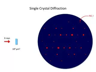
Techniques of X-ray Diffraction Laue back reflection 1. “White” x-rays scatter from a single crystal sample 2. Used to determine orientation of sample and lattice symmetry x-ray source sample film Spots appear on the film at locations determined by the Bragg condition for different (hkl) planes
2 Film or movable detector sample Monochromatic source Intensity 2 Techniques of X-ray Diffraction Debye-Scherrer powder diffraction 1. Monochromatic x-rays scatter from a finely ground polycrystalline sample 2. Used to determine lattice type and detailed crystal structure Sample is finely ground so that essentially all of the (hkl) planes that can cause diffraction are present. As a result, an intensity peak is measured for each of these planes:
Atom Molecule Cluster Bulk Solid N: 1 2-100 10-104 > 105 D. Atomic Clusters (Nanoparticles) A bulk solid can be built up as more and more atoms are combined: • Important questions: • At what value of N does a cluster of (metal) atoms begin to display bulk-like behavior? • What interesting properties do smaller clusters have, and how can they be used? The answer to #1 typically depends on what property we are interested in, so there is no universal answer.
R U = outside U = 0 inside Cluster Stability In the early 1980s a very interesting property of metal clusters was discovered: there are specific cluster sizes that are more stable than others nearby. For Na and other alkali metals these “magic numbers” are: N = 8, 20, 34, 58, 92, 138, 196, … • Why? A simple explanation: • Treat valence electrons (3s for Na) as “free” to move within the cluster volume • Solve the Schrödinger equation for a simple model potential energy function (spherical infinite potential well)
0 1g (18) (58) 2p (6) (40) Energy 1f (14) (34) 2s (2) (20) 1d (10) (18) 1p (6) (8) 1s (2) (2) Reason for “Magic Numbers” The energy level structure that comes from solving the Schrödinger equation is similar to that of the hydrogen atom, but without the same restriction on the orbital quantum number l: orbital degeneracy