Download
1 / 26
260 likes | 367 Vues
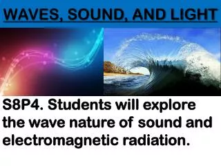
WAVES, SOUND AND LIGHT. - GRADE 12 -. Diffraction - Consider the ripple tank (equipment used to study waves) shown below…. - The image formed beneath the ripple tank consists of a series of bright lines (crests) with alternating dark lines (troughs)

E N D
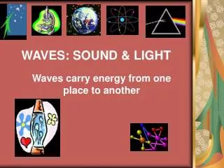
WAVES, SOUND AND LIGHT - GRADE 12 -
Diffraction • - Consider the ripple tank (equipment used to study waves) shown below… - The image formed beneath the ripple tank consists of a series of bright lines (crests) with alternating dark lines (troughs) - We now consider the situation where we place various obstacles in the path of the waves…
1) Consider placing a single barrier in the path of the wave fronts… • - The waves BEND around the edges of the barrier • - This phenomenon is known as DIFFRACTION • - The extent of diffraction is less if the wavelength of the waves is less “The bending of waves around the edges of an obstacle or opening” 2) Consider waves moving in the space between two barriers (large opening) - The waves bend around the edges of an opening - Again, the waves with the longer wavelength experiences more diffraction
3) Consider the wave pattern when we reduce the space between the barriers - The waves experience so much diffraction that they bend almost completely around the barrier edges - Once again, the degree of diffraction depends on the wavelength of the waves NOTE: It is also important to note that the wavelength (and frequency) of the waves are unchanged by the diffraction process http://www.acoustics.salford.ac.uk/feschools/waves/diffract.htm
- Huygens principle - Diffraction can be explained by Huygen’s principle “Every point on a wavefront acts as a source of secondary wavelets. The tiny wavelets spread out at the speed of the wave itself. The new wavefront is the envelope that is a tangent to all the wavelets” - A wavefront is the line joining points in the same phase - All points on a wavefront act as a source of secondary waves consisting of a series of small circular wavefronts that radiate out - The tangent to all the secondary wavelets constitute the new (second wavefront)
- Consider what happens when a wavefront arrives at an obstacle… • - The circular wave that originates at point “E” can move • around to the back of the obstacle and spread out behind • it because there are no other wavelets to interfere with it • Thus it can be said that diffraction occurs as a result of • the interference of adjacent wavelets - Interference of water waves - A set of vibrating beads create two sets of circular waves - The waves cross each other, causing the formation of a wave pattern
- The following can be observed with regards to the pattern formed when the waves overlap and the… 1) distance between the beads is varied 2) The wavelength of the waves is altered • Observations… • A new pattern is formed when the above mentioned parameters are changed • There are regions in the tank where no waves exist, but there are also • regions of strong wave creation
- The phenomenon involving the different degrees of wave formation strength can be explained by SUPERPOSITION (constructive / destructive interference) - Constructive interference results when two waves, IN PHASE, meet each other (crest and crest or trough and trough) - Destructive interference occurs when two waves that are OUT OF PHASE meet http://www.acoustics.salford.ac.uk/feschools/waves/super2.htm
Wave nature of light • - Diffraction of light • - The phenomena of diffraction and interference are properties unique to waves • - If light displays these properties is can be considered to have a wave nature • - Diffraction through a single slit Observations 1) White light (that has passed through a single slit) produces a BROAD CENTRAL BAND of white light 2) On either side of the central band there are narrower dark bands alternating with bands of spectral colours (red furthest from the central band) 3) When RED LIGHT is viewed through a single slit, a broad central band of red light is seen, along with narrower alternating black and red bands on either side 4) A similar pattern is observed for BLUE LIGHT, except that the central band for the white light is the largest and the blue light is the NARROWEST!
RED LIGHT BLUE LIGHT • Deductions… • Light has a wave nature • The White, red, blue (coloured lines) are formed when light waves • interfere CONSTRUCTIVELY! • 3) Dark bands appear when DESTRUCTIVE interference occurs! • 4) The degree (or amount) of diffraction depends on the wavelength of the light
Explanation… - Consider the figure below, depicting a single slit (with width “a”) and a screen some distance away from the slit… - Light enters the slit and according to Huygens, every point on the wavefront acts as a source of secondary wavelets that spread out in all directions - Interference will occur between the wavefronts, creating dark and bright bands
- Most of the waves moving through the slit in a straight line (no diffraction) will be in phase, resulting in the formation of a bright central maximum band - The position of dark (minimum) or bright (maximum) bands is called its ORDER, and has the symbol “m” - The first minimum (or maximum) is given the order 1 - It is written ±1 to distinguish whether it is to the left or right of the central max - The formula for the position of the MINIMA in a single–slit pattern…
- Interference of light - We have seen that light forms a diffraction pattern, but it can also form an interference pattern - Consider the setup below (double slit experiment) • Observations: • When the light is viewed through the slits, a series of alternating, equally spaced, black • and white fringes are seen • 2) When RED light is viewed, alternating black and red parallel stripes are observed • 3) When BLUE light is used, we see alternating, equally spaced, blue and black lines • 4) The Red and black stripes are WIDER than the Blue and black stripes • 5) Bright bands all the same intensity!!!
Deductions: 1) The pattern formed is an interference pattern of light waves 2) The Light, blue and red bands are a result of waves interfering that are IN PHASE (constructive interference) 3) Black stripes result from Destructive interference of waves (OUT of PHASE) 4) The stripes for the RED light are Broader than for the blue light (because Red light has a longer wavelength) 5) Light must be a wave
Doppler effect • Consider the ambulance... “The Doppler effect is the change in frequency or pitch of the sound when the sound source and the listener move with respect to each other. When the sound source is moving towards the listener, the frequency is higher than when the source is at rest, and when the source is traveling away from the listener, the frequency is lower” http://www.colorado.edu/physics/2000/applets/doppler2.html Doppler equation: http://www.astro.ubc.ca/~scharein/a311/Sim/doppler/Doppler.html http://www.youtube.com/watch?v=-d9A2oq1N38&feature=related http://www.youtube.com/watch?v=Y5KaeCZ_AaY&feature=related
- If the source is moving towards the listener, we use the formula as follows… - If the source is moving away from the listener, we use the formula as follows… Example: The siren of an ambulance emits waves at a frequency of 1000Hz. Determine the frequency of the sound heard by a stationary listener when the ambulance is moving… a) Towards the listener at a speed of 15m.s-1 b) Away from the listener at a speed of 15m.s-1
Colour • - When white light is incident on a glass triangular prism the light undergoes • dispersion and a band of colours known as the VISIBLE SPECTRUM…
- The colour of light depends on its frequency of the light waves - Each colour (frequency / wavelength) moves at the same speed in VACUUM - But when it enters a medium of a different optical density at an oblique angle, the speed of the waves decreases - Each colour moves through the prism at a different speed and each colour undergoes a different degree of refraction (bending at different angles) - Violet light has the shortest wavelength (highest frequency) and thus travels slowest through the prism, undergoing the most refraction - Red light experiences the other extreme - A rainbow forms as a result of dispersion - Light is a wave, and thus its speed can be calculated using the wave equation Note: The frequency of a wave can only be altered by changing the source, thus we associate the colour of light with its frequency rather than its wavelength
The colour of objects - Atoms and molecules contain electrons situated in energy levels - These electrons are in a constant state of vibration (vibrating at their natural frequency of vibration) - If the light incident on an object has the same frequency as the natural frequency of vibration of the electrons, they will absorb the light and begin to vibrate more vigorously - If the frequency of the light doesn’t match the natural frequency of vibration of the electrons, the atoms will absorb the energy temporarily and then re-emit it at its original frequency - In this situation, we will experience this phenomenon as reflection
Note: - For a transparent object, the light waves that are transmitted by the object are passed on by neighbouring atoms until the leave the other side. The object is said to be transparent to these frequencies - Opaque objects are objects that don’t allow light to pass through them. The colour of an opaque object is determined by the frequencies of light it reflects - Colour mixing - Mixing coloured paints and mixing coloured lights is very different - Colour mixing with light involves the ADDITION of colour - Colour mixing with paints and dyes involves SUBTRACTION of colour - ADDITION OF COLOUR - RED, BLUE and GREEN are called the primary colours of light - When all 3 primary colours of light are overlapped, WHITE light is produced - The SECONDARY colours are CYAN, MAGENTA and YELLOW and are formed by adding the primary colours - Each primary colour has a COMPLEMENTARY colour, which when mixed with the primary colour will give white light (colour triangle)
Using colour filters 1) Only allows green light through First filter allows green and blue light through 2) Second filter allows red and blue light through Result = See blue light First filter allows red light through 3) Second filter allows green light through Result = No light (darkness) First filter allows red and green light through 4) Second filter allows blue light through R + G B Result = No light (darkness) First filter allows red and blue light through 5) Second filter allows red and green light through R + B R Result = Red light First filter allows red and green light through 6) Second filter allows blue and green light through R + G G Result = Green light
- SUBTRACTION OF COLOUR - Pigment: A chemical substance that can absorb one or more frequencies of white light selectively, and reflects the remaining frequencies - Three main colours involved with pigments and dyes are: CYAN, MAGENTA and YELLOW
B G B R CYAN MAGENTA BLUE R G B YELLOW BLUE BLACK R B R G MAGENTA YELLOW RED
Colour and the television - Three separate information signals, called red, green and blue, are transmitted from a television station transmitter - In the television, there is a single tricolour picture tube that contains three electron guns (red, green and blue) - The “red” gun discharges electrons when triggered by the “red” signal, the likewise with the blue and green signals - The screen (tube) is coated with sets of small phosphor dots which are arranged in a regular pattern - As the electrons strike the phosphor dots, light is emitted - On the inside of the tube, there is a thin metal screen called a “shadow mask”. This mask ensures that electrons the red gun reach only the phosphor dots that produce red light
- At a given instant there are three separate images on the screen, one red, another blue and another green - The phosphor dots are so close to one another that the eye interprets them as a single, . continuous image