Download
1 / 22
220 likes | 311 Vues
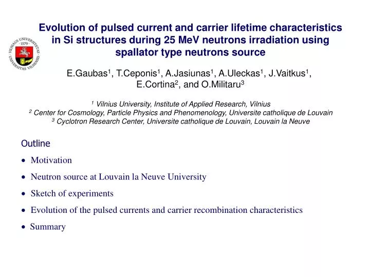
Evolution of pulsed current and carrier lifetime characteristics in Si structures during 25 MeV neutrons irradiation using spallator type neutrons source. E.Gaubas 1 , T.Ceponis 1 , A.Jasiunas 1 , A.Uleckas 1 , J.Vaitkus 1 , E.Cortina 2 , and O.Militaru 3.

E N D
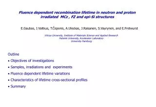
Evolution of pulsed current and carrier lifetime characteristics in Si structures during 25 MeV neutrons irradiation using spallator type neutrons source E.Gaubas1, T.Ceponis1, A.Jasiunas1, A.Uleckas1, J.Vaitkus1, E.Cortina2, and O.Militaru3 1 Vilnius University, Institute of Applied Research, Vilnius 2 Center for Cosmology, Particle Physics and Phenomenology, Universite catholique de Louvain 3 Cyclotron Research Center, Universite catholique de Louvain, Louvain la Neuve • Outline • Motivation • Neutron source at Louvain la Neuve University • Sketch of experiments • Evolution of the pulsed currents and carrier recombination characteristics Summary
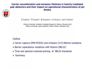
Motivation • To predict signal changes and to foresee possible modifications of the detector performance • Comparison of variations of carrier drift and recombination characteristics during neutron and proton irradiations
The energy spectrum of the out-coming neutron beam is dominated by a peak in the region of 25 MeV. Neutron source at Louvain la Neuve University Neutron spatial distribution variation with distance from thetarget The high flux neutron line is located at the Louvain la Neuve -Cyclotron. It uses aprimary 50 MeV deuteron beam that is sent on a thin beryllium target. The high cross section reaction9Be(d,n)10B produces the high flux neutron beam. To keep the gamma and charged particle contamination as low as possible filters are placedoutside the target box and fixed to the box window, made of three layers: 1 cm thick polyethylene, 1 mmCadmium and 1 mm Lead.The filter also removes from the beam the low energy neutrons.
8 m 8 m Sketch of experiments MW-PCT measurement setups
Comparison of resultsof the in situ changes of recombination lifetime during 8 MeV protons, nuclear reactor and spallator 25 MeV neutrons irradiation Reactor neutrons Spallator neutrons 8 MeV protons
U(t)=UP/PLt =At LIV ramp A=UP/PL = U/t PL= 10 ns 500 s UP= 0.01 5 V AT-DSO-6102A iC te Setup for implementation of BELIV technique Reverse bias
Comparison of resultsof changes of the barrier capacitance charging and thermal-generation current changes under nuclear reactor and spallator 25 MeV neutrons irradiation, measured in situ by BELIV technique Reactor neutrons Spallator neutrons
ICDC- induced surface charge domain drift currents: measurement setup U>UFD dy/dt - [m-1(t) +q-1(t) -Ndef-1] y(t) - [dr-1-m-1(t)]= 0, with y(t=0)=y0 and y(t=tdr)=1 Ndef=0/eNdef ;m(t)=20/em0(1-exp(-t/g)), m(t)=m0(1-exp(-t/g) ; q(t)=0/[q0exp(-t/R)/d], q(t)=q0exp(-t/R) ; tdrdr=d2/U j(t)[q0exp(-t/R)/dr]+[q0exp(-t/R)/R]+[em0dexp(-t/g)/2g]. j(t) [q0/dr], if R &g>> dr
Comparison of resultsof the on-line changes of the ICDC during 8 MeV proton beam and spallator 25 MeV neutrons irradiation 8 MeV protons Spallator neutrons Leakage current Induced charge current transients
Correlated evolution of the MW-PC, BELIV and ICDC characteristics during spallator neutrons irradiation: transients registered every 10 ms, - more than 105 on each curve; irradiation - bunches of 4 ns duration
Summary • Spallator neutron irradiations are extremely useful for in situ experiments, as electrical noises are sufficiently small in comparison with those in proton beam chamber. On-line experiments are useful to predict detector behavior in operation regime. • The observed changes of MW-PC, BELIV and ICDC transients well correlate mutually when considered relatively to an increasing fluence value. Thus, MW-PC correlated lifetime changes, measured in contact-less and distant manner, calibrated with other parameters is a powerful tool for examination in a wide dynamic range of carrier lifetimes, modified by radiation defects. Increased recombination rate in the heavily irradiated detectors may mask carrier drift. Thus, carrier recombination lifetime values, measured by MW-PC technique, can be employed in prediction of detector performance. • Approach of carrier lifetime values to those of charge drift specific time scale leads to the non-operational junction. The observed increase of generation current within BELIV transients will cause a considerable increase of detector noise level.
Acknowledgements. Development of the employed measurement techniques and instrumentation have been supported by the Research Council of Lithuania, grant MIP-054/2011, neutron irradiations were performed within frame of FP-7 “AIDA” project. E.Tuominen, J.Harkonen, and J.Raisanen are appreciated for Si samples and detectors. Thank You for attention!
Dosimetry using alanine [CH3CH(NH2)COOH –organic acid] EPR spectroscopy, - ESR of radiation created free radicals Dosimetry is based on the generation of the free radicals within the alanine pellets. Quantification of the radicals is implemented by detecting the free electrons using ElectronParamagnetic Resonance (EPR) Bruker spectrometer. Alanine dosimeter reader is calibrated to register doses between 0.05 kGy (corresponding to neutronfluence of 1012 n/cm2) and 80 kGy (corresponding to neutron fluence of 1.8 x 10¹⁵ n/cm2).
Sketch of experiments The parallel on-line measurements of MW-PC, BELIV and ICDC characteristics have been performed keeping the same experimental conditions
Fluence Φ (particles/cm2) is calculated from the integrated current, by the followingformula: Fluence (n/cm2) is directly proportional to I, integrated deuteron current (expressed in µA x hour),and inverse proportional to the distance d between the target and the sample (centimeters). Neutron source at Louvain la Neuve University Calculation of the equivalence between neutron and proton irradiation and between absorbeddose (kGy) and fluence (1 MeV eq n/cm2) Number of neutrons for several energy values and the total flux calculation Alanine dosimeter reader is calibrated to read doses between 0.05 kGy (corresponding to neutronfluence of 1012 n/cm2) and 80 kGy (corresponding to neutron fluence of 1.8 x 10¹⁵ n/cm2). The hardness factor is defined as the ratio between the displacement damage cross-section for a specificparticle energy distribution and the displacement damage cross-section of neutron of 1 MeV that has aknown value of 95MeV mb.
To evaluate the correspondence between the neutron fluence and the absorbed dose in differentmaterials (for our purpose: silicon and alanine) the KERMA values were used(sum of the kineticenergies of all the charged ionizing particles produced in the interactions: elastic scattering (n,n),inelastic scattering (n,n’γ), or (n,2n),(n,p),(n,α)…). Neutrons absorbed dose (expressed in Gy) = ∫ Φ(E)K(E)dE (integral over energy domain, 5 to 45MeV); Φ(E) is the energy distribution of the neutron beam, K(E) is the KERMA factor of the materialexpressed in fGy m2. The Φ total as 6.1 x 10¹¹neutrons/µC*Sr. The result of the integral considering the flux values and the KERMA factor is 1.52 fGy m2 . Therefore for Silicon: Dose (Gy) = 1.52 (fGy m2) x Φ (n/cm2). Neutron source at Louvain la Neuve University Equivalence between fluence (particles/cm2) and dose (Gy) References Data compilation of dosimetry methods and radiation sources for material testing, by M.Tavlet et al. CERN/TIS-CFM/IR/93-03, 1993. Calculations of the relative effectiveness of alanine for neutrons with energies up to 17.1 MeV, HM Getsenberg, Rad.Prot.Dosimetry vol 31 N ¼ (85-89), 1990. Notes on fluence normalization based on the NIEL scaling hypothesis, A.Vasilescu and G.Lindstrom, ROSE/TN/2000/02, 2000 Neutron KERMA factors for tissue and particle detector materials from 15 to 150 MeV, D. Gorbatkov, V. Kryuchkov, O. Sumaneev NIM A 388 (1997) 260-266. Updated NIEL calculations for estimating the damage induced by particles and gamma rays in Si and GaAs, A. Akkerman, J.Barak, M. Chadwick, J.Levinson, M.Murat, Y.Lifshitz Radiation Physics and Chemistry 62 (2001) 301-310
Neutron source at Louvain la Neuve University The deuteron beam has a time structure made of 4 nanosecond wide bunches with a repetition period of about 80 nanoseconds. This time structure is also reflected in the secondary neutron beam. The absolute neutron flux is estimated from the activation [4] of several metallic foils through reactions (Table 1) of known cross-sections (Fig. 2) [5].
Experience of VU team in monitoring of radiation impact on carrier recombination and generation lifetime control: Post-irradiation
Qualitative emission/ thermal generation lifetime dependence on fluence can be estimated from I-V’s Carrier generation/emission and recombination lifetimes in Si detectors (for Mrad>>n0) Nearly linear reduction of generation lifetime with enhancement of fluence is similar to that of of recombination lifetime characteristic after E.Gaubas et al JAP, 110 (2011) 033719
EC EV x Carrier recombination lifetimes (for M>>n0) Single-species (type) traps Although relaxation to equilibrium/steady-state is kept by M=pM+nM M0, n 0, S-R-H M, M>>n0, S-R-H invalid Capture coefficient <n> should be used instead of v within rigorous analysis n p J.S. Blakemore, in: Semiconductor Statistics, Ch. 8, Pergamon Press, (1962)