Download
1 / 17
170 likes | 444 Vues
THE MICROSCOPE. Chapter 7. Introduction. A microscope is an optical instrument that uses a lens or a combination of lenses to magnify and resolve the fine details of an object. The earliest methods for examining physical evidence relied solely on the microscope.

E N D
THE MICROSCOPE Chapter 7
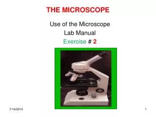
Introduction • A microscope is an optical instrument that uses a lens or a combination of lenses to magnify and resolve the fine details of an object. • The earliest methods for examining physical evidence relied solely on the microscope. • The magnified image seen by looking through a lens is known as a virtual image, whereas an image viewed directly is known as a real image. • The object to be magnified is placed under the lower lens, called the objective and viewed through the upper lens, called the eyepiece. • Various types of microscopes are used to analyze forensic specimens. THE MICROSCOPE
Types of Microscopes • Compound Microscope • Comparison Microscope • Stereoscope Microscope • Polarizing Microscope • Microspectrophotometer • Scanning Electron Microscope
The Compound Microscope • In the basic compound microscope, the object to be magnified is placed under the lower lens (objective lens) and the magnified image is viewed through the upper lens (eyepiece lens). • The magnification of the image can be calculated by multiplying the magnifying power of the objective lens times the magnifying power of the eyepiece lens. • The microscope is composed of a mechanical system which supports the microscope, and an optical system which illuminates the object under investigation and passes light through a series of lens to form an image of the specimen. THE MICROSCOPE
Figure 7–2 The principle of the compound microscope. The passage of light through two lenses forms the virtual image of the object seen by the eye.
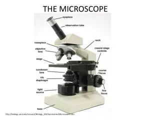
The Compound Microscope • The Mechanical System • Base: the support. • Arm: the C-shaped upright structure. • Stage: the plate on which the specimens are placed. • Body Tube: the hollow tube on which the objectives and eyepiece lenses are mounted. • Coarse Adjustment: the knob used to focus the microscope lenses by moving the body tube. • Fine Adjustment: the knob also used to focus the lenses by moving the body tube, but by a much smaller magnitude. THE MICROSCOPE
The Compound Microscope • The Optical System • Illuminator: artificial light, usually supplied by a lightbulb, to illuminate the specimen. • Transmitted Illumination: when the light is directed up through the specimen from the base. • Vertical or Reflected Illumination: when the light comes from above and reflects off the specimen. • Condenser: lens system under the microscope stage that focuses light onto the specimen. THE MICROSCOPE
The Compound Microscope • The Optical System • Objective Lens: the lens closest to the specimen; usually several objectives are mounted on a revolving nosepiece. • Parafocal: when the microscope is focused with one objective in place, another objective can be rotated into place and the specimen remains very nearly in correct focus. • Eyepiece or Ocular Lens: the lens closest to the eye. • Monocular: a microscope having only one eyepiece. • Binocular: a microscope having two eyepieces. THE MICROSCOPE
The Comparison Microscope • The comparison microscope consists of two independent objective lenses joined together by an optical bridge to a common eyepiece lens. • When a viewer looks through the eyepiece lens of the comparison microscope, the objects under investigation are observed side-by-side in a circular field that is equally divided into two parts. • Modern firearms examination began with the introduction of the comparison microscope, with its ability to give the firearms examiner a side-by-side magnified view of bullets. THE MICROSCOPE
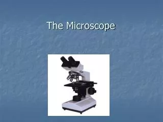
The Stereoscopic Microscope • The stereoscopic microscope is actually two monocular compound microscopes properly spaced and aligned to present a three-dimensional image of a specimen to the viewer, who looks through both eyepiece lenses. • It is particularly useful for evidence not requiring very high magnification (10x-125x). • Its large working distance makes it quite applicable for the microscopic examination of big, bulky items. THE MICROSCOPE
Figure 7–8 Schematic diagram of a stereoscopic microscope. This microscope is actually two separate monocular microscopes, each with its own set of lenses except for the lowest objective lens, which is common to both microscopes.
Polarizing Microscopy • Light that is confined to a single plane of vibration is said to be plane- polarized. • The examination of the interaction of plane-polarized light with matter is made possible with the polarizing microscope. • Polarizing microscopy has found wide applications for the study of birefringent materials (materials that split a beam of light in two, each with its own refractive index value). • The determination of these refractive index data provides information that helps to identify minerals present in a soil sample or the identity of a man-made fiber. THE MICROSCOPE
The Microspectrophotometer • The microspectrophotometer is a spectrophotometer coupled with a light microscope. • The examiner studying a specimen under a microscope can simultaneously obtain the visible absorption spectrum or IR spectrum of the material being observed. • This instrument is especially useful in the examination of trace evidence, paint, fiber, and ink evidence. THE MICROSCOPE
The Scanning Electron Microscope • Finally, the scanning electron microscope (SEM) bombards a specimen with a beam of electrons instead of light to produce a highly magnified image from 100x to 100,0000x. • Its depth of focus is some 300 times better than optical systems at similar magnification. • The bombardment of the specimen’s surface with electrons normally produces X-ray emissions that can be used to characterize elements present in the material under investigation. THE MICROSCOPE
Figure 7–16 A schematic diagram of a scanning electron microscope displaying the image of a gunshot residue particle. Simultaneously, an X-ray analyzer detects and displays X-ray emissions from the elements lead (Pb), antimony (Sb), and barium (Ba) present in the particle. Courtesy Aerospace Corp., El Segundo, Calif.