Download
1 / 20
200 likes | 615 Vues
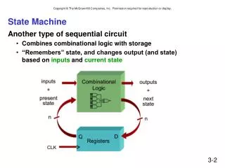
State Machine Design Procedure. 1. Build state/output table (or state diagram) from word description using state names. 2. Minimize number of states (optional). 3. State Assignment: Choose state variables and assign bit combinations to named states.

E N D
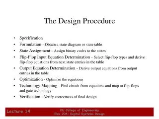
State Machine Design Procedure 1. Build state/output table (or state diagram) from word description using state names. 2. Minimize number of states (optional). 3. State Assignment: Choose state variables and assign bit combinations to named states. 4. Build transition/output table from state/output table (or state diagram) by substituting state variable combinations instead of state names. 5. Choose flip-flop type (D, J-K, etc.) 6. Build excitation table for flip-flop inputs from transition table. 7. Derive excitation equations from excitation table. 8. Derive output equations from transition/output table. 9. Draw logic diagram with excitation logic, output logic, and state memory elements.
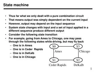
State Machine Design Example 1: 110 Detector • Word description (110 input sequence detector): • Design a state machine with input A and output Y. • Y should be 1 whenever the sequence 1 1 0 has been detected on A on the last 3 consecutive rising clock edges (or ticks). • Otherwise, Y = 0 • Note: this is a Moore machine, that is the output, Y, depends only on inputs at previous clocks rising edges , not on the current input. • Timing diagram interpretation of word description (only rising clock edges are shown): A CLK Y 0 1 1 0 0 1 1 1 0 1 1 1
State Machine Design Example 1: 110 DetectorStep1:Choosing States • Possible states (What does the state machine need to remember?): • Initial : power up, no clocks yet Y = 0 • No1s : first 1 not found Y = 0 • First1 : first 1 found Y = 0 • Two1s : at least 2 consecutive 1s found Y = 0 • ALL : found 1 1 0 Y = 1 • Are all the states needed? • Notice: Initial is equivalent to NO1s • We can drop the state Initial and replace it with state No1s
Reset State Diagram 0 1 A First1 0 NO1s 0 0 S No1s First1 Two1s ALL 0 No1s No1s ALL No1s Y 0 0 0 1 1 First1 Two1s Two1s First1 1 0 1 ALL 1 Two1s 0 1 0 Format: Arc: input A Node: state/output Y State Machine Design Example 1: 110 DetectorStep 1: State/Output Table and Diagram State Table S*
Step3: State Assignment Considerations • Why does the choice of state assignment matter? • Has a big effect on the complexity of excitation and output equations and thus on the amount of combinational logic needed. • How to find the best state assignment? • The only known way is to try all assignments and determine the resulting equations. • N = 2: (22)! = 4! = 24 assignments for 2 state bits • N = 3: (23)! = 8! = 40,320 assignments for three state bits. • N = 4: (24)! = 16! = 20,922,789,888,000 assignments for 4 state bits!!! THIS IS NOT PRACTICAL APPROACH! \ Use heuristic guidelines for pretty good assignments. This is still an active area of research! • There is no effective way to guarantee a “best” assignment. The heuristic methods sometimes perform poorly!
State Assignment Strategies • Simplest Assignment: • Straight binary, not best; purely arbitrary assignment. • One Hot Assignment: • Redundant encoding, each flip-flop is assigned a state. • Uses the same number of bits as there are states (not useful in large designs). • Simple to assign; simple next state logic (no state decoding required) • Output logic is simple! One OR gate per Moore output! • Almost One Hot Assignment: • Almost same as One Hot, but one less state bit. • Use all 0’s to represent a state (usually INIT). • Must now decode state 0 if it is needed. • Decomposed Assignment: • Use the “structure” of the state table to simplify next-state and output logic. • An “art” which requires much practice.
Example: State Assignment Strategies Alternative AssignmentsAB Q1..Q4 Q1..Q5 Q1Q2Q3 Q1Q2Q3 S 00 01 11 10 Z 0000 00001 000 000 INIT A0 A0 A1 A1 0 0001 00010 100 001 A0 OK0 OK0 A1 A1 0 0010 00100 101 010 A1 A0 A0 OK1 OK1 0 0100 01000 110 011 OK0 OK0 OK0 OK1 A1 1 1000 10000 111 100 OK1 A0 OK0 OK1 OK1 1 Almost One Decomposed Simplest One Hot Hot • Example decomposition: • Initial State = all 0’s for easy RESET • INIT state is different, so use Q1 = 1 for non-INIT states; thus D1=1 • Z = 1 in only 2 states, so use Q2 =1 for states when Z = 1; thusZ = Q2 • Use Q3 = 1 for state transitions caused by A having the value of 1 (all destination states cause by A = 1, i.e. states A1 and OK1); thus D3=A THUS, simpler next state and output logic!
State Assignment Heuristic Guidelines Starting from the highest priority to the lowest: • Choose initial coded state that’s easy to produce at reset: (all 0’s or 1’s) • This simplifies the initialization circuitry. • Freely use any of the 2n state codes for best assignment (i.e.. with s states, don’t just use the first s integers 0,1,…,s-1) • Define specific bits or fields that have meaning with respect to input or output variables (decomposed codes). • Consider using more than minimum number of state variables to allow for decomposed codes. • Minimize number of state variables that change at each transition • Simplify output logic.
A S No1s First1 Two1s ALL 0 No1s No1s ALL No1s Y 0 0 0 1 1 First1 Two1s Two1s First1 State Machine Design Example 1: 110 DetectorStep 3: State Assignment • Choose state variable assignments: • Initial state all 0s • Q2 = last A, so Q2* = A • minimize number of transitions Q1 Q2 0 0 0 1 1 1 1 0 S*
A Q1 Q2 0 0 0 1 1 1 1 0 0 00 00 10 00 Y 0 0 0 1 1 01 11 11 01 Q1* Q2* =D1 D2 Step 6 State Machine Design Example 1: 110 DetectorStep 4: Transition/Output Table • Step 4: Build transition/output table from state/output table by substituting state variable combinations instead of state names. • Step 5: Choose D Flip-Flops , so Q*= D • Step 6: Excitation table: • Same as Transition/output table with Q1*=D1, Q2*=D2
Q1•Q2 Q1 Q2 Q1 Q2 A A 00 01 11 00 01 11 10 10 0 0 1 0 0 1 1 0 0 0 0 0 1 1 1 1 0 0 D1 : D2 : 1 1 Q2•A D1 = Q1•Q2 + Q2•A D2 = A(as planned!) State Machine Design Example 1: 110 DetectorSteps 7, 8 : Excitation/Output Equations • Step 7: Excitation equations: D1, D2 = F (A, Q1, Q2) • Step 8: Output equation: Y = G (Q1, Q2) Y = Q1•Q2’ (directly read from transition table)
D D State Machine Design Example 1: 110 DetectorStep 9: Logic Diagram 1 D1 Q1 P Q Y CLK A > C Q 1 D2 Q2 Q P CLK > Q C P = Preset C = Clear Both active low CLK RESET_L RESET_L reset to initial state (active low)
State Machine Design Example 2: 110/101 Detector • Word description (110/101 input sequence detector): • Design a state machine with input A and output Y. • Y = 1 when either sequence 1 1 0 or 1 0 1 has been detected on input A on the last 3 consecutive rising clock edges (or ticks). • Otherwise Y = 0 • Note: Correct sequences may overlap and still be accepted. • Timing diagram interpretation of word description (only rising clock edges are shown): A CLK y 0 1 0 10 11 0 1 0 0 0
State Machine Design Example 2: 110/101 DetectorStep1:Choosing States • Possible states (What does the state machine need to remember?): • Idle : Initial state, no starting 1 yet Y = 0 • Got1 : A = 1 on last tick Y = 0 • Got10 : Sequence A = 10 on last two ticks Y = 0 • Got101 : Sequence A = 101 on last three ticks Y = 1 • Got11 : Sequence A = 11 on last two ticks Y = 0 • Got110 : Sequence A = 110 on last three ticks Y = 1 A CLK y 0 1 0 10 11 0 1 0 0 0 Idle Got10 Got10 Got11 Got101 IDLE Got1 Got101 Got101 Got110 Got10 Idle
A S IDLE Got1 Got10 Got101 Got11 Got110 0 IDLE Got10 IDLE Got10 Got110 IDLE Y 0 0 0 1 0 1 1 Got1 Got11 Got101 Got11 Got11 Got101 S* State Machine Design Example 2: 110/101 DetectorStep 1: State/Output Table
Reset 0 1 Got1 0 IDLE 0 0 0 0 Got10 0 Got110 1 1 1 0 0 Format: Arc: input A Node: state/output Y 1 Got101 1 Got11 0 1 1 State Machine Design Example 2: 110/101 DetectorStep 1: State Diagram
State Machine Design Example 2: 110/101 DetectorSteps 3: State Assignment • Step 3: Choose state variable assignments : • Initial state all 0s • Q1 = Y • Q3 = last A, so Q3* = A • minimum number of transitions From Step 1: A Q1 Q2 Q3 0 0 0 0 0 1 0 1 0 1 1 1 0 1 1 1 1 0 S IDLE Got1 Got10 Got101 Got11 Got110 0 IDLE Got10 IDLE Got10 Got110 IDLE Y 0 0 0 1 0 1 1 Got1 Got11 Got101 Got11 Got11 Got101 S*
A Q1 Q2 Q3 0 0 0 0 0 1 0 1 0 1 1 1 0 1 1 1 1 0 1 0 0 1 0 1 0 000 010 000 010 110 000 ddd ddd Y 0 0 0 1 0 1 d d 1 001 011 111 011 011 111 ddd ddd Unused states? Q1*Q2* Q3* =D1 D2 D3 State Machine Design Example 2: 110/101 Detector • Step 4: Transition/output table • Step 5: Choose D Flip-flops • Step 6: Excitation table • Same as Transition table
Q1 Q2 Q3 A 00 01 11 10 d 1 1 d d 1 d 00 D1 : 01 11 10 Q1 Q2 Q1 Q2 Q3 A Q3 A 00 01 11 00 01 11 10 10 d 1 1 d 1 1 1 d 1 1 1 d d 1 1 1 d 1 1 1 d d 00 00 D2 : D3 : 01 01 11 11 10 10 State Machine Design Example 2: 110/101 DetectorSteps 7: Excitation Equations • Step 7: Excitation equations • D1, D2, D3 = F (A, Q1, Q2, Q3) D1 = Q1’•Q2•Q3•A’ + Q2•Q3’•A D2 = Q2•A + Q3 D3 = A (as planned!)
State Machine Design Example 2: 110/101 DetectorStep 8: Output Equations • Step 8: Output equation • Y = Q1 (as planned!) • Step 9: Logic diagram • (3) D-Flip-flops + (3) 2-input gates + (1) 3-input AND gate + (1) 4-input AND gate • Draw the diagram. D1 = Q1’•Q2•Q3•A’ + Q2•Q3’•A D2 = Q2•A + Q3 D3 = A