Download
1 / 9
160 likes | 590 Vues
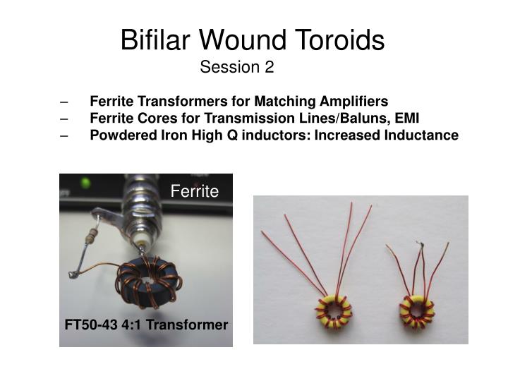
Ferrite. FT50-43 4:1 Transformer. Bifilar Wound Toroids Session 2. Ferrite Transformers for Matching Amplifiers Ferrite Cores for Transmission Lines/Baluns, EMI Powdered Iron High Q inductors: Increased Inductance. Operating Principles Right Hand Rule For a Solenoid.

E N D
Ferrite FT50-43 4:1 Transformer Bifilar Wound ToroidsSession 2 Ferrite Transformers for Matching Amplifiers Ferrite Cores for Transmission Lines/Baluns, EMI Powdered Iron High Q inductors: Increased Inductance
Operating Principles Right Hand Rule For a Solenoid Reversing Current Direction Reverses the Flux B [tesla] B I [Amps] L1 [H] I [Amps]
Operating Principles Right Hand Rule For a Solenoid A simple Experiment with a compass Demonstrated in Lab
Ideal Transformers N1=N2Identical WindingsLenz and Faraday B1 Lossless 1 mA B1+B2 =0 1 mA B2
Series Connection of InductorsBifilar Winding: AdditiveL1=L2Leq= L1+L2+2MLeq = 4L1 if M = L1 a b Wind one Inductor: 10 Turns Bifilar Lead Length = 1.5 inches Don’t solder windings yet Measure Single Turn Inductor LC mtr Solder Connections Measure Bifilar Inductor LC mtr Measure input impedance with AIM Compare Single turn and Bifilar Inductance Lbifilar #26 Gauge Yellow Core
Winding Bifilar InductorsAdditive b a a a a b b b Layout wires per top left drawing. Check continuity Connect per top right: Solder “a dot” to b
Series Connection of InductorsBifilar Winding: SubtractiveL1=L2Leq= L1+L2 - 2MLeq = 0 if M = L1 a b
4:1 Ferrite Transformer Bifilar Wound Zin = 50 Ohms Zload = 200 Ohms a b 2 mA b a Subtractive Currents No flux in Toroid 1 mA 1mA 1mA Make one transformer: 10 Turns FT50-43 material Use #26 Gauge wire and supplied BNC connector Measure input impedance with AIM Impedance meter
4:1 Ferrite Transformer Bifilar Wound Zin = 50 Ohms Zload = 200 Ohms b a a b b is ground.. Bend end up to label a dot is connected to 200 Ohm resistor Connect b dot to a : insert into center pin of connector