Download

1 / 20
200 likes | 399 Vues
Sponsor: Lenze Advisor : Professor John Chandy. Wireless User Interface for Variable Frequency Drives. Team 168 Alex Shuster (EE) Michael Kloter (EE) Christopher Perugini (EE) Kevin Wei ( EngPhys - EE) . Outline. Lenze Objectives and Deliverables Research and Proposed Solution

E N D
Sponsor:Lenze Advisor: Professor John Chandy Wireless User Interface for Variable Frequency Drives Team 168 Alex Shuster (EE) Michael Kloter (EE) Christopher Perugini (EE) Kevin Wei (EngPhys - EE)
Outline • Lenze • Objectives and Deliverables • Research and Proposed Solution • Hardware • Network Topology • Programming • Timeline • Budget • Future Work
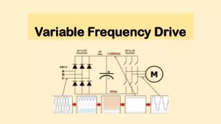
Lenze Provide Motor Control Solutions • Automotive Construction • Robotics • Manufacturing and Packaging Variable Frequency Drives • Speed and control system for AC motor
Objective - Deliverables Current Problem • Manually Set Parameters • Limited Accessibility • Long Individual VFD Programming and Reprogramming Objective • Develop a wireless interface on the VFDs • Maximize the transmission distance • Monitor and transmit to multiple VFDs at once • Able to operate in an industrial environment
Researched and Proposed Solution Researched various wireless communication options such as Wi-Fi, Bluetooth, and ZigBee Wireless Communication Choice: ZigBee • 10-100m / node • Low complexity, cost, power consumption • Low to medium data rate • Operational in an industrial environment
Hardware Develop test application to validate wireless implementation
Current Hardware Components • Sparkfun ATMEGA128RFA1 • Sparkfun RS-485 Breakout Firmware and Debug ONLY
ZigBee Lightweight Mesh • Basic data services (send and receive data) • Acknowledgements • Routing • Basic security • Power management of the radio transceiver • Network management (discovery, joining, commissioning, etc) • Advanced network operation scenarios (sleeping routers, parent-child relationship, data delivery to the sleeping nodes, etc) • Retries to send data in case of failures • Defining message payload format • Advanced security • Power management of the MCU • Interfacing hardware peripherals (ADC, PWM, EEPROM, etc)
Transceiver Schemes Option One: FIFO Byte by byte The USART will receive 8 bits, then pass that to a buffer. This buffer vector will be inserted into the ZigBee frame payload and the entire frame will be passed to the ZigBee radio frame buffer to await transmission Option Two: FIFO Message The USART will receive 8 bits, then pass that to a buffer. The MCU will wait for a full modbus message to be received 8 bits at a time and save in a message buffer This message buffer will be inserted into the ZigBeeframe payload and the entire frame will be passed to the ZigBee radio frame buffer to await transmission
Programming Options Predefined Buffer Size • Transmits when buffer filled Variable Buffer Size • Transmits when timer triggered Real Time Transmission • Transmit data as received
Predefined Buffer Size Previous Method: 8 Byte Buffer Size • Would receive data bytes from the computer and fill a buffer array of size 8, and then transmit all of the data. Downside • The Techlink software sends varying message sizes including up to 13 bytes. • The time required to transmit the full buffer can conflict with new incoming data being stored.
Variable Buffer Size More Complicated Method • Makes use of the Modbus protocol • A timer is triggered if 3.5 characters go by without data, this indicates that a complete message has been sent. • Once the timer is triggered, the buffer will be sent to the VFD. Downside • More complicated, and transmission times can interfere with receiving new data.
Transmission as Data is Received Easier method • As each data byte comes in from the computer, it is transmitted to the VFD. Downside • Greater overhead delays when the data is transmitted over ZigBee due to packetization.
Programming Choice Method Chosen: As Received • This allows for Lenze to adapt the code to other applications . • Will not restrict the use for future products.
Budget Lenze Grant: $1000
Future Work ZigBee PCB Antenna • Researched PCB Antenna Designs • Easy to tune • Reduces Costs MCU Integration • Via VFD’s RS-485 Option Module • Eliminate External Hardware • Wireless Upgrade Package