Download
1 / 36
360 likes | 504 Vues
Control and Data Networks Architecture Proposal. S. Stancu, C. Meirosu, B. Martin. Outline. Overview of the TDAQ system and networks Technology and equipment TDAQ networks: Control network - no special bandwidth requirement Dedicated data networks:

E N D
Control and Data Networks Architecture Proposal S. Stancu, C. Meirosu, B. Martin Stefan Stancu
Outline • Overview of the TDAQ system and networks • Technology and equipment • TDAQ networks: • Control network - no special bandwidth requirement • Dedicated data networks: • DataFlow network – high bandwidth (~100Gbit/s cross-sectional bw.) and minimal loss • BackEnd network – high bandwidth (~ 50Gbit/s cross-sectional bw.) • Switch management network • Conclusions Stefan Stancu
ATLAS TDAQ System/Networks High availability 24/7 when the accelerator is running Stefan Stancu
Technology and equipment • Ethernet is the dominant technology for LANs • TDAQ’s choice for networks (see [1]) • multi-vendor, long term support, commodity (on-board GE adapters), etc. • Gigabit and TenGigabit Ethernet • Use GE for end-nodes • 10GE whenever the bandwidth requirements exceed 1Gbit/s • Multi-vendor Ethernet switches/routers available on the market: • Chassis-based devices ( ~320 Gbit/s switching) • GE line-cards: typically ~40 ports (1000BaseT) • 10GE line-cards: typically 4 ports (10GBaseSR) • Pizza-box devices (~60 Gbit/s switching) • 24/48 GE ports (1000BaseT) • Optional 10GE module with 2 up-links (10GBaseSR) Stefan Stancu
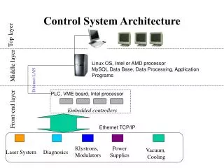
Architecture and management principles • The TDAQ networks will typically employ a multi-layer architecture: • Aggregation layer. The computers installed in the TDAQ system at Point 1 are grouped in racks, therefore it seems natural to use a rack level concentrator switch where the bandwidth constraints allow this. • Core layer. The network core is composed of chassis-based devices, receiving GE or 10GE up-links from the concentrator switches, and direct GE connections from the applications with high bandwidth requirements. • The performance of the networks themselves will be continuously monitored for availability, status, traffic loss or other errors. • In-band management – The “in-band” approach allows intelligent network monitoring programs not only to indicate the exact place of a failure (root cause analysis) but also what are the repercussions of a failure to the rest of the network.. • Out-of-band management – A dedicated switch management network (shown in blue in Figure 1) provides the communication between management servers (performing management and monitoring functions) and the “out-of-band” interface of all network devices from the control and data networks. Stefan Stancu
Resilient Ethernet networks • What happens if a switch or link fails? • Phone call, but nothing critical should happen after a single failure. • Networks are made resilient by introducing redundancy: • Component-level redundancy: deployment of devices with built-in redundancy (PSU, supervision modules, switching fabric) • Network-level redundancy: deployment of additional devices/links in order to provide alternate paths between communicating nodes. • Protocols are needed to correctly (and efficiently) deal with multiple paths in the network [2]: • Layer 2 protocols: Link aggregation (trunking), spanning trees (STP, RSTP, MSTP) • Layer 3 protocols: virtual router redundancy (VRRP) for static environments, dynamic routing protocols (e.g. RIP, OSPF). Stefan Stancu
Control network • ~3000 end nodes.Design assumption: • No end-node will generate control traffic in excess to the capacity of a GE line. • The aggregated control traffic external to a rack of PCs (with the exception of the Online Services rack) will not exceed the capacity of a GE line. • The network core is implemented with two chassis devices redundantly interconnected by two 10GE lines. • A rack level concentration switch can be deployed for all units except for critical services. • Protocols/Fault tolerance: • Layer 3 routed network • Static routing at the core should suffice. • One sub-net per concentrator switch • Small broadcast domains potential layer 2 problems remain local. • Resiliency: • VRRP in case of Router/up-link failures • Interface bonding for the infrastructure servers. Stefan Stancu
DataFlow network Stefan Stancu
DataFlow network ~100 Gbit/s Stefan Stancu
Two central switches • One VLAN per switch (AandB) • Fault tolerant (tolerate one switch failure) DataFlow network Stefan Stancu
DataFlow network • 10G ROS “concentration” • Motivated by the need to use fibre transmission (distance > 100m) • Full bandwidth provided by aggregating 10x GE into 1x10GE • Requires the use of VLANs (and MST) to maintain a loop-free topology Stefan Stancu
DataFlow network • 10G L2PU concentration • One switch per rack Stefan Stancu
DataFlow network Stefan Stancu
BackEnd network • ~2000 end-nodes • One core device with built-in redundancy (eventually two devices) • Rack level concentration with use of link aggregation for redundant up-links to the core. • Layer 3 routed network to restrict broadcast domains size. Stefan Stancu
BackEnd network ~2.5 Gbit/s ~50 Gbit/s • ~2000 end-nodes • One core device with built-in redundancy (eventually two devices) • Rack level concentration with use of link aggregation for redundant up-links to the core. • Layer 3 routed network to restrict broadcast domains size. Stefan Stancu
BackEnd network • ~2000 end-nodes • One core device with built-in redundancy (eventually two devices) • Rack level concentration with use of link aggregation for redundant up-links to the core. • Layer 3 routed network to restrict broadcast domains size. Stefan Stancu
Interchangeable processing power • Standard processor rack with up-links to both DataFlow and BackEnd networks. • The processing power migration between L2 and EF is achieved by software enabling/disabling of the appropriate up-links. Stefan Stancu
Switch Management Network • It is good practice not to mix management traffic and normal traffic. • If the normal traffic has abnormal patterns it may overload some links and potentially starve the in-band management traffic • The switch management network provides the management servers access the out-of-band interface of all the devices from the control and data networks • Flat Layer 2 Ethernet network with no redundancy. Stefan Stancu
Conclusions • The ATLAS TDAQ system (approx. 3000 end-nodes) relies on networks for both control and data acquisition purposes. • Ethernet technology (+IP) • Networks architecture maps on multi-vendor devices • Modular network design • Resilient network design (high availability) • Separate management path Stefan Stancu
Back-up slides Stefan Stancu
Option A • 1GE links • Central Sw. in SDX Stefan Stancu
Option B • 10GE links • Central Sw. in SDX Stefan Stancu
Option C • 10GE links • Central Sw. in USA Stefan Stancu
20 ROSs trunking Stefan Stancu
20 ROSs VLANs Stefan Stancu
10 ROSs single switch Stefan Stancu
10 ROSs double switch Stefan Stancu
Sample resiliency test (see [4]) MST Stefan Stancu
Sample resiliency test MST Stefan Stancu
Sample resiliency test MST Stefan Stancu
Sample resiliency test MST Stefan Stancu
Sample resiliency test MST Stefan Stancu
Control network – Online services Stefan Stancu
Control network – rack connectivity Stefan Stancu
Control network – rack connectivity Stefan Stancu
Control network – rack connectivity Stefan Stancu