Download
1 / 127
1.27k likes | 1.38k Vues
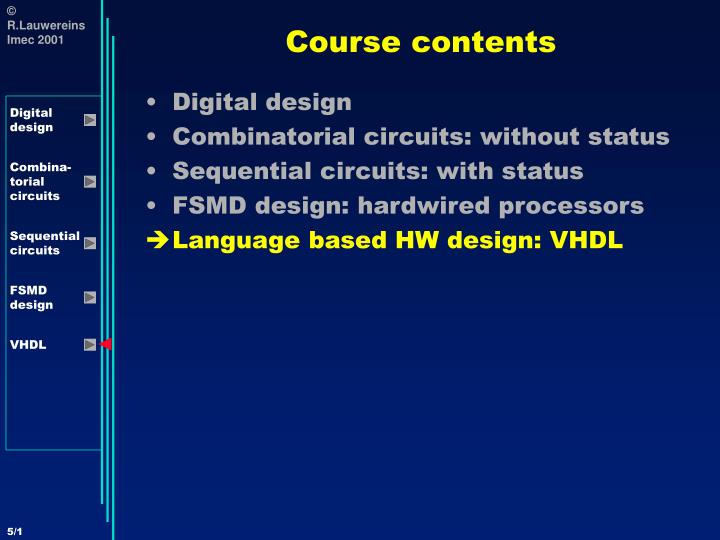
Course contents. Digital design Combinatorial circuits: without status Sequential circuits: with status FSMD design: hardwired processors Language based HW design: VHDL. Language based HW design: a VHDL primer. Introduction A first look at VHDL Signals and data types VHDL operators

E N D
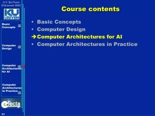
Course contents • Digital design • Combinatorial circuits: without status • Sequential circuits: with status • FSMD design: hardwired processors • Language based HW design: VHDL
Language based HW design:a VHDL primer • Introduction • A first look at VHDL • Signals and data types • VHDL operators • Concurrent versus sequential statements • Sequential construction statements • Higher performance, less portability:e.g. synthesis issues for Xilinx
Language based HW design:a VHDL primer • Introduction • A first look at VHDL • Signals and data types • VHDL operators • Concurrent versus sequential statements • Sequential construction statements • Higher performance, less portability:e.g. synthesis issues for Xilinx
VHDL primer: Introduction • Acronym: • VHDL = VHSIC Hardware Description Language • VHSIC = Very High Speed Integrated Circuit • What is VHDL? • A programming language for describing the behavior of digital systems • Design entry language, used for • Unambiguous specification at behavioral and RTL level • Simulation (executable specification…) • Synthesis • Documentation • Standardisation: IEEE 1076 • First version: 1986 • Second version: 1993 • New version about to appear
VHDL primer: Introduction • When to use VHDL instead of schematics? • Drawbacks: • VHDL is easy to learn but hard to master (semantics are quite different from software languages) • VHDL has a difficult syntax (Language sensitive editors with templates for all language constructs) • VHDL is very ‘wordy’: lots of code to type for just a few simple things • A list of instructions is less intuitive to understand than a block diagram for a human being • VHDL is designed to make simulation efficient: contains aspects that have hardly anything to do with hardware behavior, but is useful to speed-up event driven simulation
VHDL primer: Introduction • When to use VHDL instead of schematics? • Easier to capture complex circuits: higher level of abstraction with automated synthesis • you specify ‘add’ instead of jotting down a specific type of adder: the synthesis tool will instantiate the best type of adder under timing, area & power constraints • easy to parametrise (e.g. word length, queue depth) • easy to specify arrays of components • Portable across many tools for simulation, synthesis, analysis, verification, … of different vendors (e.g. Synopsys, Mentor Graphics, …)
VHDL primer: Introduction • Limitations of VHDL • The standard only describes syntax and semantics, but not the coding style • you can specify the same behavior (e.g. MUX) in an almost unlimited number of ways • each leading to a completely different implementation (e.g. Multiplexor or tri-state bus) • which is synthesis tool dependent. • You should do lots of experimentation with style-tool combinations to be able to predict how the hardware will look like that will be synthesised. Is prediction necessary? You also do not predict the ASM generated by C; C is less efficient than ASM but faster to write. Currently, it is hard to tolerate the inefficiency caused by the higher level specification for hardware. • Note: for DSP processors programmed in C, we do predict ASM and have to experiment with style-compiler combinations for efficiency reasons!!
VHDL primer: Introduction • Limitations of VHDL (ctud) • Only a subset of VHDL can be automatically synthesised; each vendor supports a different subset • Only digital; special extension (not yet widely adopted) for analog: VHDL-AMS (acronym for VHDL Analog and Mixed Signal) • IEEE standard 1076.1-1999 • is a super-set of the full IEEE VHDL 1076-1993 standard for digital design
VHDL primer: Introduction • Abstraction levels • Behavioral • Interconnected functions • Only info on functions or algorithms (what) • Only timing needed to let the function work correctly • OK for VHDL • Behavioral synthesisers immature; used for high level executable specification in top-down design and manual synthesis into RTL
VHDL primer: Introduction • Abstraction levels • RTL • Interconnected registers and combinatorial units • Info on function (what) and architecture (how) • Cycle accurate • No technology dependent timing info • OK for VHDL • Good synthesisers • Gate level • Interconnected gates and flip-flops • Info on function and architecture • Info on technology dependent timing (gate delays) • Layout • Info on layout on silicon • Continuous timing • Analog effects
VHDL primer: Introduction • Other hardware description languages (HDL) • Verilog • More widespread in USA than in Europe • Often required for gate level or RTL level ASIC sign-off • Never ending discussion which is better • PLD languages like ABEL, PALASM, … • These are more at the gate level, capturing also technology dependent features (e.g. detailed timing)
VHDL primer: Introduction • Difference between HDLs and traditional software programming languages • Concurrency: all hardware components operate in parallel • Data types: support is needed for arbitrary size integers, bit vectors, fixed point numbers • Concept of time
Language based HW design:a VHDL primer • Introduction • A first look at VHDL • Signals and data types • VHDL operators • Concurrent versus sequential statements • Sequential construction statements • Higher performance, less portability:e.g. synthesis issues for Xilinx
A First look at VHDL:Example 1 task description • Design a circuit named ‘Test’ with 3 8-bit inputs (In1, In2, In3) and two boolean outputs (Out1, Out2). The first output equals ‘1’ when the first and second input are equal; the second output equals ‘1’ when the first and third input are equal. • Let’s first make a schematic design:
A First look at VHDL:Schematic specification Test Compare Compare Out1 In1 A A EQ EQ B B In2 In3 Out2 • The circuit will be hierarchically decomposed into a top level component ‘Test’ containing 2 instantiations of a comparator component ‘Compare’
A First look at VHDL:Schematic specification Compare A A[0] XNOR B[0] AND A[1] EQ EQ B[1] B A[7] B[7] • The comparator is then hierarchically decomposed into a gate level combinatorial circuit
A First look at VHDL:Entity and Architecture Notes: - Multiple architectures per entity are possible: different ways of implementing same behavior • Declaration of the ‘Compare’ design entity: ‘Entity’ specifies the interface to the circuit, the black box of a schematic -- Eight bit comparator -- entity Compare is port( A,B: in bit_vector(0 to 7); EQ: out bit); endentity Compare; architecture Behav1 of Compare is begin EQ <= ‘1’ when (A=B) else ‘0’; endarchitecture Behav1; Input and output signals are called ‘ports’ ‘Architecture’ describes the behavior and structure of the entity, the internals of the box - This architecture specifies behavior at RTL level and not the actual structure of gates; synthesis tool will automatically translate this RTL behavioral description into gate level - Ports have an explicit direction and are (vectors of) bits
A First look at VHDL:Component and Instantiation Notes: - The two ‘comparator’ components work concurrently!!! • Specification of the next higher level in the circuit hierarchy: ‘Test’ Virtual device: allows for concurrent development of both hierarchical levels, by different persons. ‘Comparator’ will be bound to ‘Compare’ later -- Dual comparator Test component -- entity Test is port( In1,In2,In3: in bit_vector(0 to 7); Out1,Out2: out bit); endentity Test; architecture Struct1 of Test is component Comparator is port( X,Y: in bit_vector(0 to 7); Z: out bit); endcomponent Comparator; begin Compare1: component Comparator portmap (In1,In2,Out1); Compare2: component Comparator portmap (In1,In3,Out2); endarchitecture Struct1; Two instantiations of the same component ‘Comparator’ with its signal binding - This architecture describes structure, i.e. how this entity consists of an interconnection of lower level components
A First look at VHDL:Comparison with C Notes: - Only one behavior per function possible • This is very similar to software programming languages, e.g. C /* Eight bit comparator */ int Compare (int A, int B) { return (A == B); } Interface to the function Inputs and outputs are called ‘arguments’ Behavior of the function - Behavior is specified at rather high level and will be automatically translated by the compiler into ASM instructions - Function arguments do not have a direction and are of type int
A First look at VHDL:Comparison with C Notes: - The two ‘compare’ function calls are executed sequentially • This is how the higher hierarchical level looks like in C /* Dual comparator Test program */ main() { int In1, In2, In3; int Out1, Out2; Out1 = Compare(In1, In2); Out2 = Compare(In1, In3); } Two calls to the function ‘Compare’ with its argument binding - This main program is executed once and stops. In VHDL, all components describe relations that are valid continuously and forever
A First look at VHDL:Configuration • When an entity has multiple architectures, how do you indicate which one to use? • How do you bind ‘Components’ to ‘Entities’? -- Configuration information: architecture selection -- and component-entity binding configuration Build1 of Test is for Struct1 for Compare1:Comparator use entity Compare(Behav1) port map (A => X, B => Y, EQ => Z); end for; for others:Comparator use entity Compare(Behav1) port map (A => X, B => Y, EQ => Z); end for; end for; endconfiguration Build1; Both ‘use entity’s could be combined in one: for All: Comparator ... Note: ‘configuration’ corresponds in SW to ‘linking’
A First look at VHDL:Syntax ENTITY: entity Entity_name is port( Signal_name: in Signal_type; Signal_name: out Signal_type); endentity Entity_name; ARCHITECTURE: architecture Architecture_name of Entity_name is local_signal_declarations; component_declarations; begin statements; endarchitecture Architecture_name;
A First look at VHDL:Syntax Name used in component declaration Locally used name COMPONENT: component Component_name is port( Signal_name: in Signal_type; Signal_name: out Signal_type); endcomponent Component_name; COMPONENT INSTANTIATION: -- component instantiation Instance_name: component Component_name port map (Signal_list); or -- direct instantiation Instance_name: entity Entity_name(Architecture_name) port map (Signal_list); SIGNAL LIST: -- two variants: -- variant 1: ordered list of signals as in software languages -- e.g. (In1,In2,Out1) -- variant 2: named list -- e.g. (B => In2, EQ => Out1, A => In1)
A First look at VHDL:Syntax CONFIGURATION: configuration Config_name of Entity_name is for Architecture_name for Instance_name: Component_name use entity Entity_name(Architecture_name) port map (Signal_list); end for; end for; end configuration Config_name;
A First look at VHDL:Example 2 A B C Y • Declare a 3-input AND gate -- 3-input AND gate entity AND3 is port ( A,B,C: in bit; Y: out bit); endentity AND3; architecture RTL of AND3 is begin Y <= ‘1’ when ((A=‘1’) and (B=‘1’) and (C=‘1’)) else ‘0’; end architecture RTL;
A First look at VHDL:Example 2 A B C Y • Declare a 3-input OR gate -- 3-input OR gate entity OR3 is port ( A,B,C: in bit; Y: out bit); endentity OR3; architecture RTL of OR3 is begin Y <= ‘0’ when ((A=‘0’) and (B=‘0’) and (C=‘0’)) else ‘1’; end architecture RTL;
A First look at VHDL:Example 2 Y A • Declare an INV gate -- INV gate entity INV is port ( A: in bit; Y: out bit); endentity INV; architecture RTL of INV is begin Y <= ‘1’ when (A=‘0’) else ‘0’; end architecture RTL;
A First look at VHDL:Example 3 A Y B S • Build a 2-to-1 MUX using both a behavioral as well as a structural description The black box interface entity MUX21 is port ( A,B,S: in bit; Y: out bit); end entity MUX21; architecture Behav of MUX21 is begin Y <= A when (S=‘1’) else B; end architecture Behav; Behavioral description
A First look at VHDL:Example 3 A Y B S A W S Y V U B • Build a 2-to-1 MUX using both a behav. as well as a structural description architecture Struct of MUX21 is signal U,V,W : bit; component AND2 is port ( X,Y: in bit; Z: out bit); end component AND2; component OR2 is port ( X,Y: in bit; Z: out bit); end component OR2; component INV is port ( X: in bit; Z: out bit); end component INV; begin Gate1: component INV port map (X=>S,Z=>U); Gate2: component AND2 port map (X=>A,Y=>S,Z=>W); Gate3: component AND2 port map (X=>U,Y=>B,Z=>V); Gate4: component OR2 port map (X=>W,Y=>V,Z=>Y); end architecture Struct; Structural description
A First look at VHDL:Example 3 A B C Y Y Z A X Components X Y Z Entities • Assume that we want to use the previously declared AND3, OR3 and INV for this structural description of MUX configuration Use3InputGates of MUX21 is for Behav end for; for Struct for Gate1:INV use entity INV(RTL) port map (A=>X,Y=>Z); end for; for All:AND2 use entity AND3(RTL) port map (A=>X,B=>Y,C=>’1’,Y=>Z); end for; for Gate4:OR2 use entity OR3(RTL) port map (A=>X,B=>Y,C=>’0’,Y=>Z); end for; end for; end configuration Use3InputGates;
A First look at VHDL:Test bench • How can we verify the circuit that we made? • We have to apply representative stimuli • to the circuit • and check whether the outputs are correct • A VHDL ‘test bench’ can be considered to be the top level of a design • It instantiates the Design Under Test (DUT) • applies stimuli to it • checks whether the stimuli are corrector • captures the outputs for visualisation in a waveform viewer
A First look at VHDL:Test bench A MUX21 Y B S • Create a test bench for the behavioral version of the MUX entity Testbench is end entity Testbench; Testbench is self-contained: no ports architecture BehavTest of Testbench is Signal In1,In2,Select,Out : bit; begin DUT: entity MUX21(Behav) port map (In1, In2, Select, Out); Stimulus: processis begin In1<=‘0’;In2<=‘1’;Select<=‘0’; wait for 20 ns; Select<=‘1’; wait for 20 ns; In1<=‘1’;In2<=‘0’; wait for 20 ns; ... end process Stimulus; end architecture BehavTest;
A First look at VHDL:Re-use • Often, parts of a design can be re-used in another design • New products in industry often contain 95% of re-used parts and 5% is newly designed: evolutionary design • VHDL encourages this by the concept of ‘Packages’ • A ‘Package’ contains definitions of constant values, component declarations, user data types, and sub-programs of VHDL code • But first the concept ‘Library’: a library is name of directory into which the binary code resulting from analysis/compilation is stored. Default: WORK
A First look at VHDL:Re-use Package interface declaration: package Package_name is -- constants -- user defined types -- component declarations -- sub programs end package Package_name; How to use a package? use Library_name.Package_name.all; … U1: entity Package_name.Entity_name(Architecture_name);
Language based HW design:a VHDL primer • Introduction • A first look at VHDL • Signals and data types • VHDL operators • Concurrent versus sequential statements • Sequential construction statements • Higher performance, less portability:e.g. synthesis issues for Xilinx
Signals and Data Types:Predefined signal types package Standard is type Bit is (‘0’,’1’); type Boolean is (False, True); type Character is (--ASCII set); type Integer is range implementation_defined; type Real is range implementation_defined; type Bit_vector is (--array of bits); type String is (--array of characters); type Time is range implementation_defined; end package Standard; Bit, Boolean and Character are enumeration types All standard types are ‘unresolved’ (see later for the meaning of this)
Signals and Data Types:Predefined signal types Examples of integer declarations: type Year is range 0 to 99; type Memory_address is range 65535 downto 0; Checked by simulator Examples of real declarations: type Probability is range 0.0 to 1.0; type Input_level is range -5.0 to 5.0; A Bit_vector is a collection of bits; a value is specified between double quotes: constant State1: bit_vector(4 downto 0) := “00100”; LSB MSB, bit 4 A String is a collection of characters; a value is specified between double quotes: constant Error_message: string := “Unknown error: ask your poor sysop for help”;
Signals and Data Types:Predefined signal types Secondary units Time is a physical type: type Time is range implementation_defined units fs; ps = 1000 fs; ns = 1000 ps; us = 1000 ns; ms = 1000 us; sec = 1000 ms; min = 60 sec; hr = 60 min; end units; Primary unit: resolution limit Examples of use: wait for 20 ns; constant Sample_period: time := 2 ms; constant Clock_period: time := 50 ns;
Signals and Data Types:User defined physical types Metric secondary units Imperial secondary units The user may define his/her own physical types: type Length is range 0 to 1E9 units um; mm = 1000 um; m = 1000 mm; km = 1000 m; mil = 254 um; inch = 1000 mil; foot = 12 inch; yard = 3 foot; end units; Primary unit: resolution limit
Signals and Data Types:User defined enumeration types The user may define his/her own enumeration types: type FSM_states is (reset, wait, input, calculate, output); Not all synthesis tools support enumerated types When they do support them, the default encoding is often straightforward encoding using the minimum number of bits Often, the default encoding may be over-written by somewhere specifying something like “encoding_style is gray_code” or by explicitly specifying the encoding for each possible value: constant reset: bit_vector := “10000”; constant wait: bit_vector := “01000”; constant input: bit_vector := “00100”; constant calculate: bit_vector := “00010”; constant output: bit_vector := “00001”;
Signals and Data Types:Array types The user may define arrays of types: type 1D_array isarray (1 to 10) of integer; type 2D_array is array (5 downto 0, 1 to 10) of real; Keep in mind that a vector of bits has NO numerical meaning and that hence arithmetic operations on vectors of bits make no sense: signal Bus,Address : bit_vector (0 to 3); Bus <= Address + 1; -- This makes no sense!!! Solution: via operator overloading (cf. C++): - two functions ‘+’ will exist, one working on integers and one working on vectors of bits - the latter is defined in a vendor specific ‘vector arithmetic package’ that should be use’d at the beginning of your VHDL
Signals and Data Types:Standard logic • We have seen that we need more logic levels than just ‘0’ and ‘1’ (e.g. don’t care, unknown after setup violation, …) • Therefore the IEEE defined in standard number 1164 9-valued logic signals and operations on them: use always those instead of ‘bit’!! • Exists in unresolved form (std_ulogic) and resolved form (std_logic) -- again: see later for meaning • Exists in single bit and array form: • constant A: std_ulogic := ‘U’; -- unitialized • constant B: std_logic := ‘U’; • constant C: std_ulogic_vector (0 to 15); • constant D: std_logic_vector (15 downto 0);
Signals and Data Types:Standard logic library IEEE; use IEEE.Std_logic_1164.All; type std_logic is ( ‘U’, -- uninitialized e.g. after power-up ‘X’, -- strongly driven unknown e.g. after setup violation ‘0’, -- strongly driven logic zero ‘1’, -- strongly driven logic one ‘Z’, -- high impedance e.g. not driven at all ‘W’, -- weakly driven unknown ‘L’, -- weakly driven logic zero ‘H’, -- weakly driven logic one ‘-’); -- don’t care
Signals and Data Types:Assignment to signals No, because: - all statements are concurrently valid and are not executed sequentially as in SW languages - when A=‘0’ and B=‘1’, we have a short circuit A A R Z Z B B Is the following code valid? signal Z,A,B: std_ulogic; Z <= A; Z <= B; Resolver circuit
Signals and Data Types:Assignment to signals Resolver circuit signal Z,A,B: std_logic; Z <= A; Z <= B; A R Z B • VHDL is a single assignment language for unresolved data types • For resolved data types (std_logic & std_logic_vector), the resolver circuit is inferred by the synthesis tool
Signals and Data Types:Assignment to signals signal Down: std_logic_vector (3 downto 0); signal Up: std_logic_vector (0 to 3); Up <= Down; Which of the two following interpretations is correct? Up(0) Up(1) Up(2) Up(3) Down(3) Down(2) Down(1) Down(0) Up(0) Up(1) Up(2) Up(3) Down(0) Down(1) Down(2) Down(3) OR Correspondence by position! • When an array is assigned to another array, both arrays must have same size • Assignment is by position, not by index!!!
Signals and Data Types:Assignment to signals Bus(5 downto 4) <= A(0 to 1); Bus(4 downto 3) <= A(2 to 3); • Assignment to a part of an array is possible • Make sure that the direction (to or downto) is the same as in the declaration signal Bus: std_logic_vector (7 downto 0); signal A: std_logic_vector (0 to 3); Which of the following VHDL codes is correct? Direction of Bus differs from declaration Bus(0 to 3) <= A; Array sizes do not match Bus <= A; Bus(3 downto 0) <= A; OK! Bus(3) is driven by A(0) Bus(5 downto 4) <= A(0 to 1); OK! Bus(5) is driven by A(0) OK! Bus(4) is driven by A(1) and by A(2): resolved data type… use with care!!
Signals and Data Types:Assignment to signals Nibble_busA(3) Nibble_busA(2) Nibble_busA(1) Nibble_busA(0) Byte_bus(7) Byte_bus(6) Byte_bus(5) Byte_bus(4) Byte_bus(3) Byte_bus(2) Byte_bus(1) Byte_bus(0) Nibble_busB(3) Nibble_busB(2) Nibble_busB(1) Nibble_busB(0) • ‘Concatenation’: bring wire bundles together to assign them to a bigger array signal Byte_bus: std_logic_vector(7 downto 0); signal Nibble_busA, Nibble_busB: std_logic_vector(3 downto 0); Byte_bus <= Nibble_busA & Nibble_busB;
Signals and Data Types:Assignment to signals • ‘Aggregation’: alternative method to assign multiple small arrays to a bigger array • Not supported by all synthesis tools!! signal X,Y,Z,T: std_logic_vector(3 downto 0); signal A,B,C: std_logic; X <= (A,B,C,C); -- correspondence by position Y <= (3 => A, 1 downto 0 => C, 2 => B); Z <= (3 => A, 2 => B, others => C); T <= (others => ‘0’); -- initialization irrespective of width of T
Signals and Data Types:Generic constants • Allows to parameterize behavior • Enables re-use of entities in slightly changing environments • Makes VHDL much more powerful than schematic entry • Generic constants need to have a value at synthesis time! entity General_mux is generic (width : integer); port ( Input : in std_logic_vector (width - 1 downto 0); Select : in integer range 0 towidth - 1; Output : out std_logic); end entity General_mux;