Download
1 / 37
400 likes | 568 Vues
Circuit Switching. Circuit switching networks, Circuit switches-space division switches, Time division switches, Time-space-time switches, Routing in circuit switching networks, Control signaling, SS7. Switching Networks.

E N D
Circuit Switching Circuit switching networks, Circuit switches-space division switches, Time division switches, Time-space-time switches, Routing in circuit switching networks, Control signaling, SS7
Switching Networks • Long distance transmission is typically done by a network of switched nodes • Nodes not concerned with content of data • End devices are stations • Computer, terminal, phone, etc. • Data routed by switches from node to node
Nodes • Nodes may connect to other nodes only, or to stations and other nodes • Node to node links usually multiplexed • Two different switching technologies • Circuit switching • Packet switching
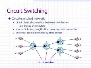
CIRCUIT-SWITCHED NETWORKS A circuit-switched network consists of a set of switches connected by physical links. A connection between two stations is a dedicated path made of one or more links. However, each connection uses only one dedicated channel on each link. Each link is normally divided into n channels by using FDM or TDM. CONNECTION ORIENTED SERVICE
Note A circuit-switched network is made of a set of switches connected by physical links, in which each link is divided into n channels.
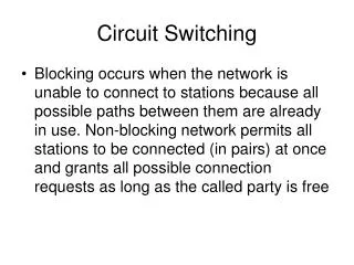
Circuit Switching • Dedicated communication path between two stations • Three phases • Establish • Transfer • Disconnect • Must have switching capacity and channel capacity to establish connection • Must have intelligence to work out routing
Note In circuit switching, the resources need to be reserved during the setup phase;the resources remain dedicated for the entire duration of data transfer until the teardown phase.
Circuit-switched network used in Example Telephone 1 is connected to telephone 7; 2 to 5; 3 to 8; and 4 to 6. Of course the situation may change when new connections are made. The switch controls the connections.
Note Switching in the traditional telephone network uses the circuit-switching approach.
Circuit Switching Concepts • Digital Switch • Provide transparent signal path between devices • Network Interface • Control Unit • Establish connections • Generally on demand • Handle and acknowledge requests • Determine if destination is free • construct path • Maintain connection • Disconnect
Circuit Switch Types • Space-Division switches • Crossbar switches • Multistage switches • Time-Division switches • Time switches • Time-space-time switches :Hybrids Time & Space switching
Space division switches • Developed for analog environment • Separate physical paths • Connection oriented service • Suitable to voice signals
1 2 … N … N –1 2 N 1 Crossbar Space Switch • N x N array of cross points • Connect an input to an output by closing a cross point • Non blocking: Any input can connect to idle output • Complexity: N2 cross points
Why crossbar switch can’t be used practically? So many numbers of cross points are impractical. Such a switch is also inefficient because statistics show that, in practice fewer than 25 percent of the cross points are in use at any given time.
Multistage Switch • Reduced number of cross points • More than one path through network • Increased reliability • More complex control • May be blocking
2(N/n)nk + k (N/n)2 crosspoints kn nk N/n N/n 1 1 1 kn nk 2 N outputs N inputs 2 N/n N/n 2 kn nk 3 3 … … … kn nk N/n N/n N/n N/n k Multistage switch Large switch built from multiple stages of small switches The n inputs share k paths through intermediate switches Larger k (more intermediate switches) means more paths to output
Note In a three-stage switch, the total number of cross points is 2kN + k(N/n)2 which is much smaller than the number of cross points in a single-stage switch (N2).
Example Design a three-stage, 200 × 200 switch (N = 200) with k = 4 and n = 20. Solution In the first stage we have N/n or 10 crossbars, each of size 20 × 4. In the second stage, we have 4 crossbars, each of size 10 × 10. In the third stage, we have 10 crossbars, each of size 4 × 20. The total number of cross points is 2kN + k(N/n)2, or 2000 cross points. This is 5 percent of the number of cross points in a single-stage switch (200 × 200 = 40,000).
In 1950s, Clos asked, “How many intermediate switches required to make switch nonblocking?” & Introduced Non blocking criteria for Multistage space switch.
Clos Non-Blocking Condition: k=2n-1 • Request connection from last input to input switch j to last output in output switch m • Worst Case: All other inputs have seized top n-1 middle switches AND all other outputs have seized next n-1 middle switches • If k=2n-1, there is another path left to connect desired input to desired output kxn nxk N/n x N/n 1 1 1 … … n-1 busy N/n x N/n Desired output Desired input kxn nxk n-1 j m n-1 busy N/n x N/n … … n+1 N/n x N/n 2n-2 nxk kxn N/n x N/n N/n Free path Free path N/n 2n-1
N2 N/2 2N2 n2 2N2 n3 2N2 n2 N2 dC dn Nn Nn Minimum Complexity Clos Switch C (n) = number of cross points in Clos switch = 2Nk + k( )2 = 2N(2n – 1)+(2n – 1)( )2 Differentiate with respect to n: 0 = = 4N – + ≈ 4N – ==> n≈ √ The minimized number of cross points is then: C* = (2N + )(2( )1/2 – 1) = 4N [(2N)1/2 – 1] This is lower than N2 for large N
16x8 8x16 144144 1 1 1 16x8 8x16 2 2 144x144 1152 outputs 1152 inputs 2 16x8 8x16 3 3 … … … 16x8 8x16 N/n 144 144x144 16 Example: Clos Switch Design • Circa 2002, Mind speed offered a Crossbar chip with the following specs: • 144 inputs x 144 outputs • Clos Nonblocking Design for 1152x1152 switch • N=1152, n=8, k=16 • N/n=144 8x16 switches in first stage • 16 144x144 in centre stage • 144 16x8 in third stage
Note According to the Clos criterion: n = (N/2)1/2 k > 2n – 1 Cross points ≥ 4N [(2N)1/2 – 1]
Example Redesign the previous three-stage, 200 × 200 switch, using the Clos criteria with a minimum number of cross points. Solution We let n = (200/2)1/2, or n = 10. We calculate k = 2n − 1 = 19. In the first stage, we have 200/10, or 20, crossbars, each with 10 × 19 cross points. In the second stage, we have 19 crossbars, each with 10 × 10 cross points. In the third stage, we have 20 crossbars each with 19 × 10 cross points. The total number of cross points is 20(10 × 19) + 19(10 × 10) + 20(19 ×10) = 9500.
Time Division Switching • Partition low speed bit stream into pieces that share higher speed stream • e.g. TDM bus switching • based on synchronous time division multiplexing • Each station connects through controlled gates to high speed bus • Time slot allows small amount of data onto bus • Another line’s gate is enabled for output at the same time
Input TDM frame with n slots Output TDM frame with k slots 1 2 n … 2 1 k … 2 1 n Time-slot interchange Time-Space-Time Hybrid Switch • Use TSI in first & third stage; Use crossbar in middle • Replace n input x k output space switch by TSI switch that takes n-slot input frame and switches it to k-slot output frame kxn nxk N/n x N/n 1 1 1 nxk N inputs 2 nxk 3 … nxk N/n
Flow of time slots between switches • Only one space switch active in each time slot First slot First slot N/n N/n k n n k 1 1 1 k n n k 2 2 N/nN/n 2 … … … k n n k N/n N/n N/n N/n kth slot kth slot k
Space stage TSI stage TSI stage kxn TDM n slots TDM k slots nxk TDM k slots 1 1 kxn nxk n slots N/n x N/n Time-shared space switch N outputs 2 N inputs 2 kxn nxk n slots 3 3 … … n slots kxn nxk N/n N/n Time space time Switch using Time multiplexed space switch • Very compact design: fewer lines because of TDM & less space because of time-shared crossbar
Time-space-time switch by using time multiplexed space switch
Example: T-S-T Switch Design For N = 960 • Single stage space switch ~ 1 million cross points • T-S-T • Let n = 120 N/n = 8 TSIs • k = 2n – 1 = 239 for non-blocking • Pick k = 240 time slots • Need 8x8 time-multiplexed space switch
Circuit Switching - Applications • Inefficient • Channel capacity dedicated for duration of connection • If no data, capacity wasted • Set up (connection) takes time • Once connected, transfer is transparent • Developed for voice traffic (phone)