Download
1 / 29
580 likes | 1.17k Vues
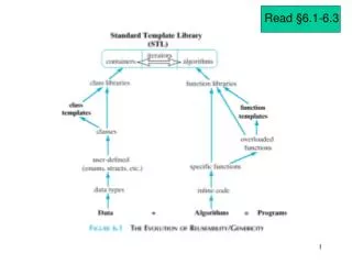
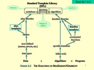
6.1 Polyphase System 6.2 Notations 6.3 Single-phase Three-wire Systems 6.4 Three Phase connection 6.5 The Delta ( ) Connection 6.6 Power measurement. Engineering Circuit Analysis. CH6 Polyphase Circuits. Ch6 Polyphsae Circuits. 6.1 Polyphase System.

E N D
6.1 Polyphase System 6.2 Notations 6.3 Single-phase Three-wire Systems 6.4 Three Phase connection 6.5 The Delta ( ) Connection 6.6 Power measurement Engineering Circuit Analysis CH6 Polyphase Circuits
Ch6 Polyphsae Circuits 6.1 Polyphase System Polyphase system : system with polyphase sources Single source (Vs) Notice the instantaneous voltage maybe zero The instantaneous power will be zero They all have 120o phase differences The instantaneous power will never be zero. Poly sources ( )
Ch6 Polyphsae Circuits 6.1 Polyphase System • The incident with a zero instantaneous power has been exempted. • The source power can be delivered more stably. • The polyphase systems can provide multiple output voltage levels. • Polyphase systems in practice certain sources which maybe approximated • by ideal voltage sources, or ideal voltage sources in series with small • internal impedances.
a b e d f c j g i h l k Ch6 Polyphsae Circuits 6.2 Notations For note c : For note f : For note j :
Ch6 Polyphsae Circuits 6.2 Notations The voltage of point a with respect to pointb a +; b -; Similarly, Iab denotes the current from point a to b. Test with graphical analysis ? (Using the phasor diagram)
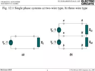
Ch6 Polyphsae Circuits 6.3 Single-phase Three-wire Systems Function: allowing household electronics operating at two levels of voltages to be applied. Voltage characteristics 1-phase 3-wire Source Household electronics may either operate with or with Phase characteristics
Ch6 Polyphsae Circuits 6.3 Single-phase Three-wire Systems Current characteristics This is no current in the neutral wire. How if the two are NOT equal, and all the wires have impedances ? This is a more practical scenario.
Ch6 Polyphsae Circuits 6.3 Single-phase Three-wire Systems • Example 9.1 (P242) • Determine the power delivered to the and the Loads. rms ② Determine the power lost in the three lines represented by respectively. and ③ Determine the transmission efficiency? rms total power absorbed by the loads η = total power generated by the sources Hints: observe a structure with regular meshes and know impedances, we can determine the currents I1, I2 and I3 in order to find out the power being lost and delivered!
Ch6 Polyphsae Circuits 6.3 Single-phase Three-wire Systems Apply KVL for the three meshes. Rearrangingthem in a matrix form as
Ch6 Polyphsae Circuits 6.3 Single-phase Three-wire Systems If can be calculated: Hence, the average power delivered to each of the loads are: Total loaded power
Ch6 Polyphsae Circuits 6.3 Single-phase Three-wire Systems Power lost in three wires are: Total lost power Transmission efficiencyη Total power generated by the two voltage sources is: Transmission efficiency
6.4 Three Phase connection Ch6 Polyphsae Circuits Voltage characteristics Balanced three-phase sources (phasor voltages)
6.4 Three Phase connection Ch6 Polyphsae Circuits Positive phase sequence (abc) (clockwise rotation) Negative phase sequence (cba) (Anti-clockwise rotation)
6.4 Three Phase connection Ch6 Polyphsae Circuits Line-to-line voltages (take the abc sequence as an example) Hence verifies KVL.
6.4 Three Phase connection Ch6 Polyphsae Circuits Voltage types magnitude Phasor difference Phase voltages ( ) Line-to-line voltages ( )
6.4 Three Phase connection Ch6 Polyphsae Circuits Current characteristics
6.4 Three Phase connection Ch6 Polyphsae Circuits Consider three impedances are connected between each line and the neutral line. Hence When balanced impedances areapplied to each of the three lines and the neutral line carries no current.
6.4 Three Phase connection Ch6 Polyphsae Circuits Example 9.2 (P247) Phase voltages: line-to-line voltage: Line currents: Power absorbed by the three loads
6.4 Three Phase connection Ch6 Polyphsae Circuits Example 9.2 (P247) How about the instantaneous power? Note: Van = 200V rms Similarly , the instantaneous total power absorbed by the loads are : The total instantaneous power is NEVER ZERO.
6.4 Three Phase connection Ch6 Polyphsae Circuits • Example 9.3 (P249) A balanced three-phase system with a line voltage of 300Vrms is supplying a balanced Y-connected load with 1200W at a leading power factor (PF) of 0.8. Determine line cuurent IL and per-phase load impedance Zp. The phase voltage is: Vp = 300/ Vrms. The per-phase power is: 1200W/3 = 400W. Therefore , and IL = 2.89Arms The phase impedance is: A leading PF of 0.8 implies the current leads the voltage, and the impedance angle is: -argcos(0.8) = -36.9o and Zp = 60 -36.9oΩ Note: the apparent power of a Y-Y connected load is P = Van × IAN (phase voltage × line current)
6.5 The Delta ( ) Connection Ch6 Polyphsae Circuits The neural line dose not exist. Balanced impedances are connected between each pair of lines.
6.5 The Delta ( ) Connection Ch6 Polyphsae Circuits Voltage characteristics Phase voltages Line voltages ﹠ Current characteristics Phase currents Line currents
6.5 The Delta ( ) Connection Ch6 Polyphsae Circuits connections connections √ Phase voltages Line voltages √ √ Phase currents Line currents √
6.5 The Delta ( ) Connection Ch6 Polyphsae Circuits • Example 9.5 (p251) Determine the amplitude of line current in a three-phase system with a line voltage of 300Vrms that supplies 1200W to a Δ-connected load at a lagging PF of 0.8. The per-phase average power is: 1200W/3 = 400W Therefore, 400W = VL ∙ IP ∙ 0.8 = 300V ∙ IP ∙ 0.8, and IP = 1.667Arms The line current is: IL = IP = 1.667A = 2.89Arms Moreover, a lagging PF implies the voltage leads the current by argcos(0.8) = 36.9o The impedance is: Note: the apparent power of a Δ connected load is P = Vab × IAB (line voltage × phase current)
Ch6 Polyphsae Circuits 6.6 Power measurement Wattmeter measured by potential coil measured by current coil current coil Passive Network potential coil E.g.
Ch6 Polyphsae Circuits 6.6 Power measurement 1 2 Validate the power meter reads the actual power absorbed/delivered by the three impedances.
reactive (PF=0) capacitive / inductive (0<PF<1) resistive (PF=1) Ch6 Polyphsae Circuits 6.6 Power measurement
. . . 1 N . 2 Wattmeter 1 reads and : Ch6 Polyphsae Circuits 6.6 Power measurement with positive phase sequence. (1) Find the reading of each wattmeter. (2) The total power absorbed by the loads. With positive phase sequence , we know : Example 9.7 (p256)
. . . 1 N . 2 Wattmeter 2 reads and : Ch6 Polyphsae Circuits 6.6 Power measurement Wattmeter 1 reads : Hence , Example 9.7 (p256)