Download
1 / 28
280 likes | 476 Vues
Status of ATF Damping Ring low vertical emittance studies. 2009.10. K. Kubo. ATF Damping Ring (KEK). Extraction and Final Focus Test Beam Line. Test Facility for LC Test of Low emittance beam tuning Deliver low emittance beam, e.g. for final focus test (ATF2)

E N D
Status of ATF Damping Ring low vertical emittance studies 2009.10. K. Kubo
ATF Damping Ring (KEK) Extraction and Final Focus Test Beam Line • Test Facility for LC • Test of Low emittance beam tuning • Deliver low emittance beam, e.g. for final focus test (ATF2) • R & D of instrumentations, etc. Circumference: 139 m Energy: 1.3 GeV Injector Linac Required or target of low vertical emittance Original design: 12 pm Assumption in ATF2 design: 12 pm ILC damping ring design: 2 pm
Low Emittance Tuning Three consecutive corrections • COD correction • Vertical COD-dispersion correction • Coupling correction Monitor: BPM (Beam Position Monitors) (total 96) Corrector: Steering magnets (47 horizontal and 51 vertical) Skew Qauds (trim coils of sextupole magnets, total 68)
+ I - I /2 - I /2 - I /2 - I /2 + I Skew correctors - trim coils of sextupole magnets The trim windings of all 68 sextupole magnets have been arranged to produce skew quadrupole fields, used as correctors. Currents of the top and the bottom poles are the same. Currents of other poles are one half. (Suggested by T. Raubenheimer) Skew Quad Field by Sextupole Magnet
Low Emittance Tuning • COD correction: using steering magnets, minimize BPM reading and , :x(y): horizontal (vertical) BPM reading. (b) V-COD-dispersion correction: using steering magnets, minimize dispersion and orbit y: measured vertical dispersion. r : weight factor = 0.05 (c) Coupling correction: using skew quads, minimize vertical response to horizontal steering x(y): horizontal (vertical) position change at BPM due to excitation of a horizontal steering magnet. Two horizontal steering magnets were used (Nsteer=2). About (n+1/2)p phase advance between the two.
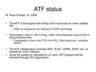
Old History of low emittance in ATF DR By 2004, we confirmed very low emittance beam, around 4 pm. Since then, pursuit of low emittance had not been a major study item. The emittance deteriorated. Over the past year, renewed efforts have been made for low emittance. by H. Hayano
Recent efforts for low emittance Re-Alignment of magnets Related to beam measurement • BBA (Beam Based Alignment) measurement • Optics matching (Beta-beat correction) • ORM (Orbit Response Matrix) analysis Effectiveness of each still needs to be understood.
DR Magnet Level Measurement No data for SF, SD and QF1R in the first three measurements. Smooth curves from fitting M. Takano
Deviation from smooth curve Improved? RMS(DY) [mm]MAR08: 0.086 APR08: 0.084 OCT08: 0.076 NOV08: 0.057 FEB09: 0.056 M. Takano
Beam Based Alignment Simulation of the tuning showed importance of BPM - magnet center offset error Emittance vs. BPM offset error with respect to the nearest magnet
Magnet (quad or skew quad) BPMs BPMs BPM Beam Based Alignment - Method T. Okugi • Make vertical local bump at the Magnet-BPM. • 2. Change Magnet strength. • 3. Measure the orbit difference for all the BPMs. • Normal Quads: Vertical, Skew Quads: Horizontal • 4. Estimate the minimum orbit difference point. Trim winding of sextupole magnets
Beam Based Alignment - results RMS of beam position change at all (except for noisy) BPMs vs. local bump amplitude. Fitted as Examples Bump at Skew Quad (Sextupole) Bump at Quad T. Okugi Typical error of offset: ~ 30 mm for Quad ~ 80 mm for Skew Quad
Optics matching (Beta-beat Correction) Calculated vertical beta functions of two different optics matching conditions. December 1999, when we observed small vertical emittance (about 5pm). May 2008, when we could not achieve low emittance. Beta-beat can increase emittance sensitivity to errors.
Optics matching (Beta-beat Correction) • Start from setting a “design” optics. (2008 fall) • Measure beta-function at every quadrupole magnet • Beta-beat was observed. Correction based fully on the model • We tried three (?) times. Results were different from the calculations. • Our model was not good enough for this methods. (?) Partially rely on model, partially empirical method Concentrate on vertical beta-function at QF1Rs (vertical beta-beat in arc sections) • Look for quadrupole magnets whose change would partly correct the beta-beat at QF1Rs from optics model. • Some improvement
Optics matching (Beta-beat Correction) Vertical beta-function at all quadrupole magnet of one family in the arc sections. (Should be flat for matched optics.) Before and after a beat correction. (Example) Not completely satisfactory. Need more study for better modeling. But condition was improved.
ORM Analysis • Measure changes in the closed orbit with respect to changes in strength of a number of orbit correctors • Fits a machine model to the data, by adjusting: • Quadrupole strengths, • BPM gains and couplings, • Corrector magnet strengths and tilts. Need more studies for understanding how to use information from ORM.
Coupling correction using ORM Analysis ORM analysis effectively projects the betatron coupling sources onto the skew quadrupoles Determination of skew quadrupole strengths required to cancel the coupling sources Possible limitations • Present analysis do not include orbit distortion • which can affect predictions of effects of correctors • will be tried after BBA and more accurate orbit corrections • Degeneracy between errors causing apparent coupling
ORM Analysis • Correlation between • Changes in skew quadrupole strengths determined from ORM analysis, and • Known changes in currents applied to correctors Deviations from the straight line indicate error of present model.
Recent history of emittance in ATF DR Vertical emittance < 10 pm (from Laser Wire measurement) Smaller than limits of other monitors? S. Kuroda and N. Terunuma
Example of DR Laser Wire measurement s = 8.6 mm (convolution of beam size and laser size) H. Shimizu
Summary and Future Plans • Low emittance tuning and efforts for improving DR emittance • Re-alignment • BBA (BPM - Magnet offset measurement) • Optics matching (Beta-beat correction) • ORM (Orbit Response Matrix) analysis • The emittance performance has been recovered. • ey< 10 pm in April and May 2009. Good enough for FF test. • Effectiveness of each item for this recovery is not clear yet. • Plans for smaller emittance (2 pm is ILC DR design.), • More simulation studies on the tuning procedure • Analysis of beam measurement, e.g. ORM. • Upgrade of all BPM electronics (20 out of 96 BPMs were already upgraded) • Re-alignment of magnets.
Emittance vs. BPM offset w.r.t. nearest magnetwith two different magnet misalignment Average of 100 seeds 90% CL (90th among 100 seeds) 1999 data and 2008 data used different measurement methods. Measurement error may be dominant in2008 data. Can not tell change of alignment conditions from these data.
Result of tuning simulation, 3 optics Number of random seeds giving resultsEmittance vs. BPM-Magnet offset error For some random seeds, SAD cannot find closed orbit, betafunctions, etc. The left figure shows number of seeds out of 100, which give results. The reason was not well studied and how to treat these results is not clear.
Beam Based Alignment Position at BPM outside local bump vs. amplitude of bump Examples Bump at Skew Quad Bump at Quad
Example of data from coupling correction Changes in vertical orbit response to a horizontal steering. Measurement and prediction from present model. Change of Response at all BPM to one horizontal steering magnet. Measured April 10, 2009
ORM Analysis Response of all BPMs to all horizontal steering magnets (But omitted if error<0.03) Measured April 10, 2009