Download
1 / 20
200 likes | 286 Vues
Low emittance tuning. ILC-MAC 21/09/2006. Tuning simulations. Using SAD (K. Kubo). K. KUBO, ILCDR CERN meeting. J. Jones - MOPLS140- EPAC06. BPMs and dipole correctors were placed at every quadrupole magnet in the lattice, and skew quadrupoles at every sextupole .

E N D
Low emittance tuning ILC-MAC 21/09/2006 Global Design Effort
Tuning simulations Using SAD (K. Kubo) Global Design Effort
K. KUBO, ILCDR CERN meeting Global Design Effort
J. Jones - MOPLS140- EPAC06 • BPMs and dipole correctorswere placed at every quadrupole magnet in the lattice, and skew quadrupoles at every sextupole. • Alignment errors are assumed to be randomly Gaussian distributed within 2 sigma. Global Design Effort
Coupling correction • Minimisation of cross-plane response Matrices using skew-quadrupoles. • The coupled motion is excited by horizontal kickers, and the vertical motion on a set of BPMs analysed to determine the relative amount of coupling. • The choice of horizontal kickers affects the coupling signal seen. • 4 horizontal kickers were used: 2 were spaced with a phase difference of π/2, the other 2 with a phase sum of π/2. Global Design Effort
Ground motion • The ground is assumed to have an A coefficient of 100£gm/10m/Year. • The simulation is initially seeded with the alignment tolerances given in Table 1 the ring was then allowed to move under the influence of ATL motion. • Emittance tuning every 6 days is sufficient to maintain the vertical emittance below the target of 20nm-rad over the 4 months period. Global Design Effort
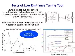
ATF - Low emittance tuning • Vertical dispersion after COD and dispersion correction. • Measured before and after improvement of BPMs readout circuits and other beam based optics updates. Y. Honda et al, “Achievement of Ultralow Emittance Beam in the Accelerator Test Facility Damping Ring,” Phys. Rev. Lett. 92, 054802-1(2004). Global Design Effort
ATF - Low emittance tuning Vertical dispersion and coupling correction are iterated 4pm Vertical emittance measured with laser wire in the ring vs. bunch intensity Global Design Effort
ATF - Low emittance tuning M.D. Woodley et al. MOOCH01-EPAC04 Global Design Effort
I.L.C. Damping Rings RF System HIGH ac option Global Design Effort R. Boni – INFN-LNF
D.R. MAIN RF PARAMETERS 3.5 MWELECTRON RING BEAM POWER1.75 MW +POSITRON RINGS 1.75 MW RF VOLTAGE46.6 MVin e- and e+RINGS Global Design Effort R. Boni – INFN-LNF
HIGH RF VOLTAGE SUPERCONDUCTIVE RF or …. CESR CRYO-MODULE KEK-B CRYO-MODULE Length ~ 3.5 m Transverse Diameter ~ 1.5 m Global Design Effort R. Boni – INFN-LNF
The system is powerful enough to meet the specifications in case of one RF station fault 30 mt straight section KLYSTRON Global Design Effort
32 CRYO-MODULES per RING 8 RF STATIONS per RING Global Design Effort R. Boni – INFN-LNF
32 CRYO-MODULES input power 53 - - - 125 kW acc. gradient 6.3 - - - 7.2 MV/m per SC cavity 12 CRYO-PLANTS 520 W each @ 4.5K wall-plug 175 kW each 8 KLYSTRONS 650 MHz - 0.5 MW Global Design Effort R. Boni – INFN-LNF
30 mt straight section BEAM POWER3.5 MW e- RING RF VOLTAGE 46.6 MV 8 KLYSTRONS 650 MHz - 0.8 MW input power 53 ÷ 125 kW acc. gradient per cavity 6.3 ÷ 7.2 MV/m 12 CRYO-PLANTS 520 W each @ 4.5K wall-plug 175 kW each The system is powerful enough to meet the specifications in case of one RF station fault Global Design Effort
RF units • The modification of the frequency from 500 to 650 MHz requires to re-design the cryo-module. In fact, the cavity shape must be scaled from 500 MHz; the input coupler and the HOM dampers must be re-designed too. The input coupler is the most critical element in a new 650 MHz structure, mainly because the power handling capability, that is about 260 kW-CW in the 500 MHz system, must be of comparable level in the new design. Scaling the HOM dampers, wrapped around the beam pipe warm sides, does not appear a hard work. Finally, the cryostat must be considerably renewed, especially the cavity LHe tank, for the smaller cavity dimensions and the “warm-to-cold transitions”. Anyhow, the large number of needed cryo-modules justifies the effort of developing a new unit. • RF sources • The RF stations will consist of the CW 650 MHz klystron supplied by its CW Power Supply. New RF power sources are necessary. Klystrons of power and frequency close to the needed ones exist on the market and can be modified by the manufacturer, with a moderate R&D effort. The RF industry [1] is available to develop the new power source. HV power supplies for this type of klystrons are in operation at DESY. Ferrite circulators for the klystron protection can be developed too. Products with similar specifications are being operated in other laboratories. Global Design Effort
Cryo-modules In the light of the information and discussions with other users, we deem that a realistic cost of each fully equipped 650 MHz cryo-module would be about …M€ and that the R&D cost of the new module should be considered as an extra unit (1/96) RF Stations Information from the industry, gives a cost of about …k€ per/klystron. This price includes the focusing coils. In this case too, the R&D, necessary to develop a new unit, is estimated like the cost of an additional item (1/24). Global Design Effort