Download
1 / 35
350 likes | 497 Vues
CesrTA. Low Emittance Program. David Rubin Cornell Laboratory for Accelerator-Based Sciences and Education. Low Emittance Tuning. Objectives Develop strategies for systematically tuning vertical emittance Rapid survey Efficient beam based alignment algorithm

E N D
CesrTA Low Emittance Program David Rubin Cornell Laboratory for Accelerator-Based Sciences and Education
Low Emittance Tuning Objectives • Develop strategies for systematically tuning vertical emittance • Rapid survey • Efficient beam based alignment algorithm • Demonstrate ability to reproducibly achieve our target of 5-10pm (geometric) • In CesrTA this corresponds to a vertical beam size of about ~10-14 microns • Enable measurement of instabilities and other current dependent effects in the ultra low emittance regime for both electrons and positrons For example - dependencies of • Vertical emittance and instability threshold on density of electron cloud • Cloud build up on bunch size • Emittance dilution on bunch charge (intrabeam scattering) TILC08
Low Emittance Tuning Outline • Horizontal emittance in a wiggler dominated ring • Sensitivity of horizontal emittance to optical and alignment errors • Contribution to vertical emittance from dispersion and coupling • Dependence of vertical emittance on misalignments of guide field elements • Beam based alignment • Alignment and survey • Dependence on BPM resolution • Beam position monitor upgrade • Beam size monitors • Intensity dependent effects • First experiments with low emittance optics • Experimental plan TILC08
Wiggler Emittance Dependence of emittance on number of wigglers Zero current emittance In CesrTA - 90% of the synchrotron radiation generated by wigglers TILC08
Minimum horizontal emittance Can we achieve the theoretical horizontal emittance? How does it depend on optical errors/ alignment errors? Correct focusing errors - using well developed beam based method • Measure betatron phase and coupling • Fit to the data with each quad k a degree of freedom • Quad power supplies are all independent. Each one can be adjusted so that measured phase matches design • On iteration, residual rms phase error corresponds to 0.04% rms quad error. residual dispersion in wigglers is much less than internally generated dispersion • We find that contribution to horizontal emittance due to optical errors is neglible. • Furthermore we determine by direct calculation that the effect of of misalignment errors on horizontal dispersion (and emittance) is negligble We expect to achieve the design horizontal emittance (~2.3nm) TILC08
Sources of vertical emittance • Contribution to vertical emittance from dispersion • Dispersion is generated from misaligned magnets • Displaced quadrupoles (introduce vertical kicks) • Vertical offsets in sextupoles (couples horizontal • dispersion to vertical) • Tilted quadrupoles (couples x to y) • Tilted bends (generating vertical kicks) • Contribution to vertical emittance from coupling • Horizontal emittance can be coupled directly to vertical • through tilted quadrupoles TILC08
Effect of misalignments For CesrTA optics: Introduce gaussian distribution of alignment errors into our machine model and compute emittance TILC08
Dependence of vertical emittance on misalignments nominal For nominal misalignment of all elements, v < 270pm for 95% of seeds TILC08
Misalignment tolerance Contribution to vertical emittance at nominal misalignment for various elements Target emittance is 5-10pm TILC08
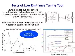
Beam Based Alignment • Beam base alignment algorithms and tuning strategies (simulation results) • Beam based alignment of BPMs(depends on independent quad power supplies) • Y < 50m • Measure and correct • -phase design horizontal emittance • Orbit reduce displacement in quadrupoles (source of vertical dispersion) • Vertical dispersion minimize vertical dispersion • Transverse coupling minimize coupling of horizontal to vertical emittance • Minimize -phase error with quadrupoles • Minimize orbit error with vertical steering correctors • Minimize vertical dispersion with vertical steering correctors • Minimize coupling with skew quads TILC08
One parameter correction • CESR correctors and beam position monitors • BPM adjacent to every quadrupole (100 of each) • Vertical steering adjacent to all of the vertically focusing quadrupole • 14 skew quads - mostly near interaction region • The single parameter is the ratio of the weights • Three steps (weight ratio optimized for minimum emittance at each step) • Measure and correct vertical orbit with vertical steerings minimize i (wc1[kicki]2 + wo [yi]2 ) • Measure and correct vertical dispersion with vertical steering minimize i (wc2[kicki]2 + w[i]2) • Measure and correct coupling with skew quads minimize i (wsq[ki]2 + wc[Ci]2) TILC08
Tuning vertical emittance • Evaluate 6 cases 2 sets of misalignments: 1. Nominal and 2. Twice nominal(Worse) X 3 sets of BPM resolutions: 1. No resolution error, 2. Nominal, and 3.Worse (5-10 X nominal) v=109m May 07 survey (one turn) ~ 27m (Nturn average) ~ 27m/N *The actual error in the dispersion measurement is equal to the differential resolution divided by the assumed energy adjustment of 0.001 TILC08
Low emittance tuning Vertical emittance (pm) after one parameter correction: With nominal magnet alignment, we achieve our target emittance of 5-10pm for 95% of seeds with nominal and worse BPM resolution With 2 X nominal magnet alignment, one parameter correction is not adequate TILC08
Two parameter correction Consider a two parameter algorithm Measure orbit and dispersion. Minimize i wc2[kicki]2 + wo2 [yi]2 + w1[i]2 Measure dispersion and coupling. Minimize i wsq[ki]2 + w2[i]2 + wc[Ci]2 The two parameters are the ratio of the weights. The ratios are re-optimized in each step Vertical emittance (pm) after one and two parameter correction: 2 X nominal survey alignment, 10m relative and 100m absolute BPM resolution - 2 parameter algorithm yields tuned emittance very close to target (5-10 pm) for 95% of seeds TILC08
Alignment and Survey Instrumentation - new equipment Digital level and laser tracker Network of survey monuments Complete survey in a couple of weeks Magnet mounting fixtures that permit precision adjustment - beam based alignment TILC08
BPM resolution Relative BPM resolution critical to measurement of vertical dispersion Dispersion depends on differential orbit measurement v = [y(/2) - y(-/2)]/ ~1/1000 In CesrTA optics dependence of emittance on vertical dispersion is v ~ 1.5 X 10⁻⁸ 2 Emittance scales with square of relative BPM error (and the energy offset used to measure dispersion) (single pass) ~ 27m (N turn average) ~ 27m/N Note: (nominal) ~ 2m Achieve emittance target if < 10m TILC08
Beam Position Monitor System • Presently have a mixed dedicated digital system with twelve stations and a coaxial relay switched analog to digital system with ninety stations. • Digital system stores up to 10 K turns of bunch by bunch positions with a typical single pass resolution of ~ 30 microns. • From the multi-turn data, individual bunch betatron tunes can be easily determined to < 10 Hz. • Digital system will be fully implemented within the next year TILC08
Beam Position Monitor System • BPM resolution TILC08
Beam Size Measurements • Conventional visible synchrotron light imaging system for light from arc dipoles for both electrons and positrons with a vertical beam size resolution of ~ 140 microns. • 32 element linear photomultiplier array enables multi-turn bunch by bunch vertical beam size measurements using the same electronics as the digital beam position monitor system. • A double slit interferometer system using the same 32 element linear photomultiplier array. Anticipated resolution • ~ 100 micron single pass bunch by bunch vertical beam size resolution • 50 micron multi-pass bunch by bunch vertical beam size resolution • X-ray beam size monitor • Bunch by bunch 2-3 m resolution • One each for electrons and positrons TILC08
Point-to-point Imaging optics X ray beam size monitor Concept detector Arc dipole monochromator l Synchrotron Radiation ~ 1-10 keV Damping ring Machine parameters DAQ R Data Processing And analysis Feedback to operations, machine studies, simulations TILC08
Intensity dependent effects • Emittance • Intrabeam scattering Depends on amplitude and source (dispersion or coupling) of vertical emittance IBS has strong energy dependence (~-4) Flexibility of CESR optics to operate from1.5-5GeV will allow us to distinguish IBS from other emittance diluting effects. TILC08
Intensity dependent effects Lifetime As we approach our target emittance of 5-10pm and 2x10¹⁰ particles/bunch Touschek decreases to ~10 minutes. TILC08
Initial experiments with low emittance optics • 6 Wiggler low emittance optics - h ~ 7.5nm - 2.085GeV Wiggler triplet TILC08
Emittance tuning • 6 wiggler optics • x~7.5nm Coupling < 1% TILC08
Dispersion Wigglers are located between 18-19 and 80-81 Correction of horizontal dispersion is required TILC08
6 wiggler optics • Dispersion IR is primary source of vertical dispersion Vertical dispersion In order to achieve v < 5pm, we require 2 < 9mm TILC08
Touschek Lifetime 6 wiggler, 1.89GeV optics 11-September 2007 preliminary TILC08
Lifetime • Lifetime vs current - 6 wiggler low emit optics • - x~7.5nm • 2.085GeV positrons 29-february-2008 preliminary TILC08
Lifetime vs current - 6 wiggler low emit optics - x~7.5nm positrons and electrons 29-february-2008 TILC08
Dispersion • AC dispersion measurement Dispersion is coupling of longitudinal and transverse motion • -Drive synchrotron oscillation by modulating RF at synch tune • Measure vertical & horizontal • amplitudes and phases of signal at synch tune at BPMs • Then • {v/v}= (yamp/zamp) sin(y- z) • {h /h}= (xamp/zamp) sin(h- z) • Advantages: • 1. Faster (30k turns) • 2. Better signal to noise - • filter all but signal at synch tune “measured c_12” - 30k turn simulation “model c_12” - Model y-z and x-z coupling “model eta” - Model dispersion TILC08
System status • Status of beam based measurement/analysis • Instrumentation - existing BPM system is 90% analog with relays and 10% bunch by bunch, turn by turn digital • Turn by turn BPM - - A subset of digital system has been incorporated into standard orbit measuring machinery for several years - Remainder of the digital system will be installed during the next year • Software (CESRV) / control system interface has been a standard control room tool for beam based correction for over a decade • For measuring orbit, dispersion, betatron phase, coupling • With the flexibility to implement one or two corrector algorithm • To translate fitted corrector values to magnet currents • And to load changes into magnet power supplies • ~ 15 minutes/iteration TILC08
Experimental program • Cesr TA low emittance program • 2008 • Install quad leveling and adjustment hardware new hardware simplifies alignment of quadrupoles • Extend turn by turn BPM capability to at large fraction of ring • Commission 2GeV 2.3nm optics [12 wigglers, CLEO solenoid off] Survey and alignment Beam based low emittance tuning • Commission positron x-ray beam size monitor (~2m resolution) • Install spherical survey targets and nests and learn to use laser tracker More efficient survey and alignment • 2009 • Complete upgrade of BPMs Single pass measurement of orbit and dispersion • Commission electron x-ray beam size monitor • 2010 • Complete program to achieve ultr-low emittance TILC08
Correlated misalignment • Correlated misalignment - temperature dependence • Magnets move as tunnel warms with operation • Temperature change is not uniform - slowly varies along circumference • (dy/dT)T < 30m Slow wave y = Asin(kns+) kn=2n/circumference A< 30m, < 1pm TILC08
Time dependence of survey Is the survey stable? Short time scale • Measured quadrupole vibration amplitude at frequency > 2Hz is less than 1m Corresponding to y << 2pm TILC08
Time dependence of survey Is the survey stable? Long time scale For most quads nominal alignment (~150m) is preserved for at least a year A few magnet stands will have to be secured TILC08