Download
1 / 16
160 likes | 356 Vues
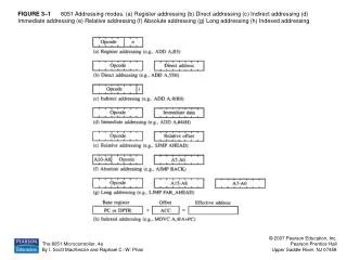
Seokkee Kim and Soo-Ik Chae System Design Group School of Electrical Engineering Seoul National University 2005 / 05 / 05. Implementation of a Simple 8-bit Microprocessor with Reversible Energy Recovery Logic. Contents. Introduction to nRERL 8-bit nRERL Microprocessor Phase Scheduling

E N D
Seokkee Kim and Soo-Ik Chae System Design Group School of Electrical Engineering Seoul National University 2005 / 05 / 05 Implementation of a Simple 8-bit Microprocessor with Reversible Energy Recovery Logic
Contents • Introduction to nRERL • 8-bit nRERL Microprocessor • Phase Scheduling • Reversibility Breaking • Measurement Results • Future Works
fi+1 fi+2 fi+3 fi fi+1 fi+2 G H F Xi+1 Xi G-1 H-1 F-1 fi+3 fi+4 fi+5 fi+3 fi+4 fi+2 Introduction to nRERL (1) • nRERL is nMOS Reversible Energy Recovery Logic *) • A Fully adiabatic circuit using reversible logic • Only nMOS SW is used by exploiting Bootstrapped • Phase-pipelining using 6-phase clocked power *) J. Lim, D.-G. Kim, and S.-I Chae, “nMOS reversible energy recovery logic for ultra-low-energy applications,” IEEE Journal of Solid-State Circuits, vol. 35, no. 6, pp. 865-875, June, 2000.
T0 T1 T2 T3 T4 T5 T6 Forward Logic switch Vdd fi Forward Isolation switch fi+1 fi 0 Vdd fi+1 MFL n1 0 Xi+1 MFI Vdd Xi fi+2 0 clamp MFLB n2 Vdd fi+3 MFIB 0 Xi Vdd-Vthb Xi MRI n3 MRL Vdd n1 Xi+1 0 MRIB Reverse Logic switch n4 MRLB Reverse Isolation switch Vdd-Vthb Xi+1 0 fi+3 fi+2 Vdd n3 0 Introduction to nRERL (2)
8-bit nRERL Microprocessor (1) • Issues • Area v.s Reversibility • How we should control the reversibility to integrate the microprocessor in the limited silicon area ? • Pipelining v.s Energy • How we should schedule the phase pipelining to minimize the total energy consumption of the microprocessor ? • Energy v.s Reversibility • How we could control the reversibility without increasing the total energy consumption of the microprocessor ?
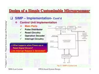
ROM (64w x 20b) Program Counter(PC) Branch PC Generator fREF fOSC 8-bit nRERL Microprocessor (2) • A subset of DLX Instruction Set Architecture • No floating point Instructions • 19 Instructions • 5 macro-blocks: • IF ID EXE MEM WB • Fully adiabatic circuit • 6-phase CPG is also integrated • A shared off-chip inductor is used 8-bit adiabatic Microprocessor Controller ALU RAM (128w x 8b) Register File (16w x 8b) Off-chip clocked power 6-phase Clocked Power Generator data flow path
T17 T6 T12 T7 T8 T9 T10 T11 T13 T14 T15 T16 T5 T1 T2 T3 T4 T0 Time 0 1 2 3 4 5 0 0 1 2 3 4 5 1 2 3 4 5 Phase Register File ALU Memory Writeback data Buffer Register File ALU Memory Writeback data Register File ALU Memory Writeback data Phase scheduling (1) CASE I: Cycle-based scheduling CASE II: Phase-based Scheduling (best case) CASE III: Phase-based Scheduling (worst case)
T0 T6 T12 T18 T1 T2 T3 T4 T5 T7 T8 T9 T10 T11 T13 T14 T15 T16 T17 T19 T20 T21 T22 T23 Time 1 2 3 4 5 1 2 3 4 5 1 2 3 4 5 0 0 0 0 1 2 3 4 5 Phase Buffer MUX Data path Control Signal Write data Forward data Page register forward External Instruction ALU RAM Register File Memdata ROM PC register Control Eqcheck branch pc generation Branch Flush write to register Decoded Instructions pc increment Instruction Fetch Instruction Decoding /Register Fetch Execution Memory Acess Writeback Overhead Phase scheduling (2)
f0 f1 T2 T3 T4 T5 T6 T7 T8 f2 SERC f4 Data* 0 f4 f5 f3 f1 f2 0 Data Vthb n7 n7 Data* 0 Data* Data* Vthb n8 f5 f4 0 Reversibility Breaking (1) • SERC: Self-Energy Recovery Circuit • Energy recovery with its own data instead of using reversible logic • Nonadiabatic loss exists ( )
wd[m]_wr_iso_f1 wd[m]_wr_f2 bit[n]_out Read port wd[m]_rd_iso_f2 wd[m]_rd_f3 Write port SERC in Memory Cell wd[m] _unwr_f4 (ref_f4) wd[m] _unwr_f5 (ref_f4) Reversibility Breaking (2) • Infinite memory cannot be implemented on the limited silicon area • SERC is used for unwrite and refresh operations.
Measurement Results • ANAM 0.18m (1P6M) • Core: 2.62 x 2.03 mm2 • CPG: 1.0 x 0.6 mm2 • Vdd=1.8V, Vth0=0.35V • E=8.5 pJ/cycle (P=7.5 W) • @ Vdd=1.8V, f=880kHz • E_cpg = 4.97 pJ/cycle • (58.5%) • E_core = 3.53 pJ/cycle • (41.5%) microprocessor core Control Bias Bias generator ALU & Register file ROM & PC Memory 6-phase Clocked Power Routing CPG
Energy Partitions • The energy portion of CPG is more than a half. • More optimization is required for CPG design. • At optimal condition, Adiabatic, Leakage, CPG rail-driver energy loss should be same. <Partitioned by functional blocks> <Partitioned by energy components>
Comparisons (1): CMOS v.s nRERL • Minimum Energy Consumption
Future Works • More energy-efficient CPG design is required. • More study on the complexity reduction is required for the implementation of more complex circuits.*) *) Seokkee Kim and S.-I Chae, “Complexity reduction in an adiabatic microprocessor using reversible logic,” will be published on proc. International Symposium on Low Power Electronics and Design, Aug., 2005.