Download
1 / 30
360 likes | 602 Vues
CSE598A/EE597G Spring 2006. Current Source & Bias Circuits. Insoo Kim, Kyusun Choi Mixed Signal CHIP Design Lab. Department of Computer Science & Engineering The Pennsylvania State University. Introduction. Required Features of Current Source High Rout Wide Operation Range

E N D
CSE598A/EE597G Spring 2006 Current Source & Bias Circuits Insoo Kim, Kyusun Choi Mixed Signal CHIP Design Lab. Department of Computer Science & Engineering The Pennsylvania State University
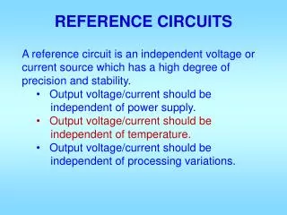
Introduction • Required Features of Current Source • High Rout • Wide Operation Range • Constant Current Source • Low PVT (Process, Voltage, Temperature) Sensitivity • Required Features of Bias Circuit • Low Rout • Low PVT Sensitivity
Current Source Basic Current Source Wilson Current Mirror Cascode Current Mirror
Simple NMOS Current Source What’s the bad feature of this?
Cascode Current Source What’s the bad feature of this?
Basic Current Mirror What’s the bad feature of this?
Wilson Current Mirror What’s the drawback of this circuit?
Cascode Current Mirror But, it still has limited output swing problem.
Bias Circuits Self Bias Circuits PTAT Bias Circuits Band gap Reference
Power Supply Dependency of Current Source Consideration Factors - VDD - Channel Length Modulation - Transistor Mismatch How do we generate Iref independent of the supply voltage?
Self Biasing Circuit What’s role of Rs? What’s the advantage of these circuits? What’s the problem of these circuits?
Improved Self Biasing Circuit Improved Circuit with Start-up Circuit * This Circuit is practical only if Improved Circuit eliminating Body Effect
0℃ 90℃ M1(Ids) Negative TC Positive TC ZTC (Zero Temperature Coefficient) VDD VDD M1(Vgs) A Simple Temperature Compensation Concept vr0 v M1 R1 1. R1 is a conductor which has positive TC 2. M1 has negative TC below ZTC point (Semiconductor) 3. If we control Vr0 below ZTC point, Vr0 become less sensitive to temperature due to opposite TC of M1 and R1 Self Bias Circuit
starter ⓐ ⓑ For Temp. Compensation pmos diode Vext ⓑ vref ⓐ Case Study (I) – Self Bias Circuit in DRAM What’s the drawback of these circuits?
vr1 Voltage Buffer ⓐ starter For Temp. Compensation ⓐ Case Study (II) – Self Bias Circuit in DRAM Why does this circuit need the voltage buffer? Why are PMOS current mirrors stacked in the reference bias circuit?
VBE Referenced CMOS Self-bias Circuit How do we fabricate BJT in CMOS Process Technology? * Temperature Sensitivity ~ - 4000 ppm/C
Thermal Voltage Referenced CMOS Self-Bias Circuit * Temp. Sensitivity ~ +3300 ppm/C
CMOS Band gap Reference What’s the problem?
(cont’d) CMOS Band gap Reference Actual Implementation of CMOS Band Gap Reference
Design Lab. – Self Bias Circuit with Temp. Compensation • Schematics * AMIS 0.5um Tech (a) Basic Schematic (b) actual implementation
Design Lab. – Self Bias Circuit with Temp. Compensation • Simulation Results VDD Vr0b Vr0 (a) Vr0 (b)
Design Lab. – Self Bias Circuit with Temp. Compensation • Simulation Results – Temp. Compensation 90C 90C 25C 25C (a) (a) -10C -10C (b) (b) Vr0 Current
90C 25C -10C Design Lab. – Self Bias Circuit with Temp. Compensation • Zero Temperature Coefficient Point 0.82V
References • Joongho Choi, “CMOS analog IC Design,” IDEC Lecture Note, Mar. 1999. • B. Razavi, “Design of Analog CMOS Integrated Circuits,” McGraw-Hill, 2001. • Hongjun Park, “CMOS Analog Integrated Circuits Design,” Sigma Press, 1999.