Download
1 / 18
180 likes | 304 Vues
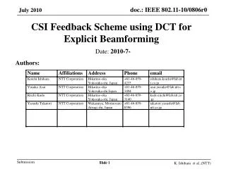
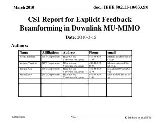
Time Domain CSI report for explicit feedback. Date: 2010-05-17. Authors:. Abstract. MU-MIMO technology essentiality for TGac is no longer to demonstrate We need to make sure that this technology is efficient and performant.

E N D
Time Domain CSI report for explicit feedback Date: 2010-05-17 Authors:
Abstract • MU-MIMO technology essentiality for TGac is no longer to demonstrate • We need to make sure that this technology is efficient and performant. • In [1], it has been shown that with explicit feedback, the amount of uncompressed MU-MIMO CSI report was increasing strongly compared to SU-MIMO CSI report • As this important feedback duration can strongly affect MAC efficiency for MU-MIMO and reduce its usage, • It was accepted that a deeper reflection on compressed MU-MIMO was needed • In this presentation, we show that the time representation of the channel provides an important compression of the feedback information • By optimizing the transfer function between the frequency and the time domain, we show that this compression even leads to improvements of the performances Slide 2
Frequency domain and time domain representations of the channel: interest toward time domain feedback • By construction, the impulse response of the channel is not longer than the cyclic prefic duration CP • In the time domain, the feedback of the taps of the channel (Ntap <= CP) is sufficient to retrieve the complete channel state information • It's then obvious that a CSI feedback in the time domain could get a compression gain at least equal to 4 over a CSI feedback in the frequency domain, without any loss of information • CSI feedback in the frequency domain lead to the feedback of a correlated information Feedback Feedback Frequency domain Time domain Representation of the channel Slide 3
Frequency domain and time domain representations of the channel: interest toward time domain feedback • Explicit feedback of the impulse response of the channel: compressed feedback • Sum up of the mathematical process: Hf,STA htime Hf,AP FftFtf • First straightforward assumption: Fft can be an iDFT and Ftf can be a DFT STA AP Sounding LS frequency channel estimation Hf, STA Transfer matrix (frequency to time domain) Fft Feedback of only the significant taps (nb samples <=CP) Feedback detection htime Time domain channel impulse response htime Transfer matrix (Time to frequency domain) Ftf frequency channel estimates Hf, AP G Slide 4
Finding channel impulse response based on the frequency channel estimation: case of iDFT for Fft (1/4) • Assuming the channel impulse response of the channel with i, j the index of the transmit and receive antennas l the index of the taps, τ,h the delay and amplitude/phase of each tap CP the number of samples in the cyclic prefic • The result of an iDFT applied to frequency domain least square LS channel estimates equals to with N=NFFT, the OFDM FFT size M=NMOD, the number of modulated subcarriers (1) Slide 5
Finding channel impulse response based on the frequency channel estimation: case of iDFT for Fft (2/4) • If NMOD=NFFT, • Following equation (1), the channel impulse response is located in the first CP elements of the time domain vector htime, as we wanted • The reason for that is because the transfer matrix iDFT is well conditioned (conditional number of 1 for a squared iDFT) NFFT Amplitude Fft 1 NFFT iDFT NFFTxNFFT Singular values of Fft 0 0 NFFT Slide 6
Finding channel impulse response based on the frequency channel estimation: case of iDFT for Fft (3/4) • However, due to the tone allocation with guard and DC null subcarriers, NMOD <NFFT • Following equation (1), the channel impulse response is no longer located only on the first CP elements of the time domain vector htime, which is now problematic • The reason for that is because the transfer matrix iDFTmod is not well conditionned (conditionnal number >> 1) NFFT Amplitude NMOD NMOd 1 Fft iDFT NFFTxNFFT NFFT Singular values of iDFTmod NMOD NMOD iDFTmod 0 0 NMOD Slide 7
Finding channel impulse response based on the frequency channel estimation: case of iDFT for Fft (4/4) • However, due to the tone allocation with guard and DC null subcarriers, NMOD < NFFT • When performing an IDFT on the frequency domain channel estimate vector for an OFDM symbol • the estimate of the channel impulse response is corrupted with inter-tap interference, that spreads the impulse response far beyond the CP first samples • The compression gain is partially lost NMOD NMOD Frequency domain Time domain Slide 8
How to find a Fft better than iDFT • In order to improve the detection of the channel impulse response when NMOD < NFFT, by reducing the inter tap interference, a solution is to find a new matrix Fft with a reduced conditional number • This reduction can be done by performing a truncated SVD on iDFTmod, by keeping unchanged the singular values before the truncated threshold Th and set to zero the singular values after the threshold • The new transfer matrix Fft is now a truncated iDFT (TiDFT). The transfer matrix Ftf can stay as a DFT Amplitude NMOD Hf,STA htime Hf,AP Fft Ftf 1 Fft TiDFT DFT NMOD TiDFT G 0 NMOD 0 Th Singular values of iDFTmod Singular values of TiDFT Mathematical representation of the general feedback Slide 9
How to find a Fft better than iDFT • In order to improve the detection of the channel impulse response when NMOD < NFFT, by reducing the inter tap interference, a solution is to find a new matrix Fft with a reduced conditional number • This reduction can be done by performing a truncated SVD on iDFTmod, by keeping unchanged the singular values before the truncated threshold Th and set to zero the singular values after the threshold • The new transfer matrix Fft is now a truncated iDFT (TiDFT). The transfer matrix Ftf can stay as a DFT NMOD NMOD TiDFT Frequency domain Time domain Slide 10
How to find a Fft better than iDFT • In order to find the optimum threshold, it's even more interesting to evaluate the impact of the truncation on the general feedback process, by looking at the matrix G = TiDFT x DFT • The matrix G1 = iDFT x DFT with NFFT=NMOD is well conditioned because iDFT is well conditioned • The matrix G2 = iDFTmod x DFT with NFFT<NMOD is not well conditioned, because iDFTmod is not well conditioned • We want the matrix G3 = TiDFT x DFT with NFFT<NMOD to be well conditioned 1 1 1 Target 0 0 0 0 0 NFFT NMOD 0 NMOD G3 = TiDFT x DFT G2 = iDFTmod x DFT G1 = iDFT x DFT Singular values of general matrix G Slide 11
1 0 NMOD 0 Th Singular values of iDFTmod Singular values of TiDFT How to find a Fft better than iDFT • In order to find the optimum threshold, it's even more interesting to evaluate the impact of the truncation on the general feedback process, by looking at the matrix G3 = TiDFT x DFT • If we truncate to much, we will loose all the useful information • If we don't truncate enough, we won't see any changes • With this optimal threshold • Not only will we suppress most of the inter-tap interference, and the noise on the last NMOD-CP samples of the time domain response • But on the top of that, we will enable additional noise reduction by suppressing the singular values of G carrying no significant useful information • Note that the threshold will be optimal independently of the channel as its optimization depend only on the tone allocation 1 0 0 NMOD Singular values of G3 = TiDFT x DFT Slide 12
Frequency domain explicit feedback Time domain explicit feedback with iDFTmod Time domain explicit feedback with TiDFT Chan E 40MHz Time domain explicit feedback performance results • Time domain explicit feedback outperforms frequency domain explicit feedback when using the proposed TiDFT by almost 10dB • Time domain explicit feedback with a classical iDFT suffers from an error floor due to inter-tap interferences • Note that frequency domain explicit feedback corresponds here to least square (LS) frequency channel estimation • Note also that the results with TiDFT are obtained with an optimum threshold Th=53 (optimisation and matrices in annex) Time domain explicit feedback: feedback of the first CP samples of the channel impulse response Slide 13
Conclusion • Feedback compression mechanisms are important for MAC efficiency improvements of explicit feedback DL MU-MIMO • Time domain explicit feedback is a very efficient solution to reduce the size of the feedbacks • In order to keep all its advantages, we propose a transfer function called TiDFT which enables an efficient compression and improves the quality of the estimates compared to both iDFT time domain and frequency domain explicit feedbacks. Slide 14
References [1] Ishihara, K. and Yasushi, T., CSI Report for Explicit Feedback Beamforming in Downlink MU-MIMO, IEEE 802.11-10/0332r0, Mar. 2010 Slide 15
Annexes Slide 16
How to find a Fft better than iDFTFinding the optimum Th, example of 40MHz • The figure presents the singular values of the G matrix (representing the general feedback process) obtained for different Th for the TiDFT (Fft) • The value of Th=53 is the closest from the target. • For 40MHz a TiDFT with Th=53 will present the best performance Singular values Singular values index Slide 17
Sensitivity to quantization:Time domain vs Frequency domain feedbacks • MSE for the complete (quantized or not) feedback process without noise • Time domain feedbacks are not more sensitive to quantization: • Min of 6 bits for frequency or time domain explicit feedbacks Slide 18