Download

1 / 22
220 likes | 407 Vues
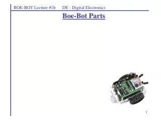
Programming Boe-Bots (Part 1). Slides taken from: WAM tutorial, and course material developed by Dean Brock and Tammy Gammon. Module Components. Serial Signal Conditioning Conditions voltage signals between PC serial connection (+/- 12V) and BASIC Stamp (5V) for Programming.

E N D
Programming Boe-Bots (Part 1) Slides taken from: WAM tutorial, and course material developed by Dean Brock and Tammy Gammon
Module Components Serial SignalConditioningConditions voltagesignals between PC serialconnection (+/- 12V) and BASIC Stamp (5V) for Programming. 5V RegulatorRegulates voltageto 5V with a supply of 5.5VDC to 15VDC EEPROMStores the tokenized PBASIC program. ResonatorSets the speed at whichinstructions are processed. Interpreter ChipReads the BASIC program from the EEPROM and executes the instructions.
Module Pins Pins 5-20:Input/Output (I/O)pins P0 through P15 Pin 1: SOUT Transmits serial data during programming and using theDEBUG instruction Pin 24: VIN Un-regulated input voltage (5.5-15V) Pin 23: VSS Ground (0V) Pin 2: SIN Receives serial data during programming Pin 22: RES Reset- LOWto reset Pin 3: ATN Uses the serial DTR line togain the Stamps attention for programming. Pin 21: VDD Regulated 5V. P0 P15 P1 P14 Pin 4: VSS CommunicationsGround (0V). P2 P13 P3 P12 P4 P11 P5 P10 P6 P9 P7 P8
The Board of Education makes it easy to connect devices, power up and program. 5V regulator Battery Servo Connections Wall DCSupply Power Header Power OnLight I/O Header Breadboard Serial ProgrammingPort Reset Switch Off/Module Power/Servo Power
A Simple Program • Enter your first program into the BASIC Stamp Editor. • Notice that different code appears in different colors. This is a great help in writing correct code!
'Running' Your Program • Download, or Run your program by clicking the Run button. • The DEBUG Window should appear showing your message.
How a Program is Placed on the Module • The program is tokenized,or converted into symbolic format. • Tokenizer • The tokenized program is transmitted through the serial cable and stored in EEPROM memory. • The Interpreter Chip reads the program from EEPROM and executes the instructions. • A program is writtenin the BASIC Stamp Editor.
Directives Directives are special instructions to the Editor ensuring the the code is tokenized for the correct PBASIC version and for the correct BASIC Stamp. • When starting a new program, be sure to click the buttons to add these directives to your program.
DEBUG Window • When a program contains a DEBUG command, the Editor opens the DEBUG Window. • Data is sent back through the serial cable as characters to be viewed. This data is sent very quickly! • The RESET button on board will start the program on your Stamp again. Hello, it's me, your BASIC Stamp!
Program like you are an engineer • Organize and structure your code. • Use indentation to clarify organization. • Indent loops and code skipped by if’s • Use white space wisely. • Follow a consistent style and format. • Use comments to explain your code. input 14 ‘push button – normal timing • Use variable and loop names which clarify purpose.
The Program Header • Identify the code. • Your name • Project Title • Date • Title/file of code • Briefly state purpose of code.
Good Program Structure • Header • Define the constants green con 0 • “Declare” the pins input 14 ‘push button for normal timing output green ‘green LED • Declare and comment your variables n var byte ‘index for varying blink rate
I/O Pin “Language” • input 14 ‘normal mode pushbutton if in14 then …… • output 0 ‘green led out0 = 0 pause 500 out0 = 1 • You don’t even have to declare output: low green pause 500 high green
Declaring & Assigning Variables • A variable & its size must be declared: normal var bit ‘allocates 1 bit (0 or 1) x var nib ‘nibble, 4 bits (0 – 15) y var byte ‘byte, 8 bits (0 – 255) counter var word ‘16 bits (0 – 65,535) • Variables contain values which can be changed. Examples: normal = in14 normal = ~normal counter = counter + 1
If …. then Function • Arithmetic and logical operators may be used in the test condition. • A bit of code… if in14 = 0 then normal_mode if in14 = 0 and in7 = 0 then non_resp • Why wouldn’t you want to list if…then statements as shown?
For….next • Iterative loop • Example to create varying pause times: x var nib for x = 1 to 10 … pause 200 * x … next
Of course, we must mention… • goto label ‘creates continuous loop • ‘or skips to another part of program • And all happily ever-afters finish with a “the end” or just END in PBASIC.
Sensors • A microcontroller-controlled system changes its outputs according to its input signals • A sensor is an input device used to detect or measure. • Example: push-button
Push-Button Sensor OPEN (Not pressed) CLOSED (Pressed)
Sample Code input 2 ‘push button recheck: if in2 = 0 then blink goto recheck blink: …make some led blink goto recheck