Download
1 / 12
130 likes | 143 Vues
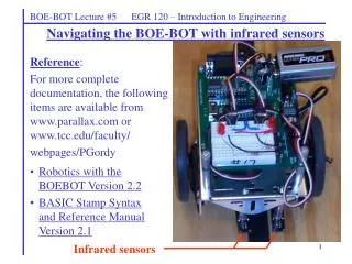
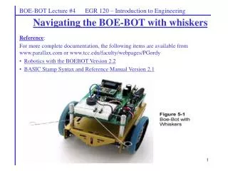
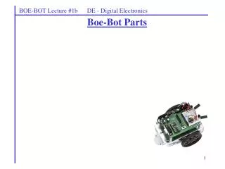
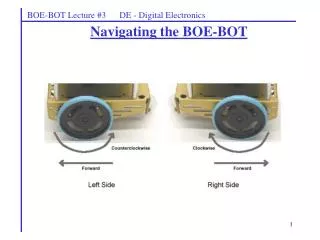
BOE-BOT Lecture #1b DE - Digital Electronics. Boe-Bot Parts. Connections : Connect the serial port (COM1) on the computer to the serial port on the BOE. Connect the battery pack to the BOE. Turn the switch on the BOE to position 1 or 2. Computer. Basic Stamp Editor.

E N D
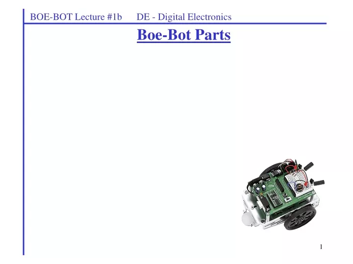
BOE-BOT Lecture #1b DE - Digital Electronics Boe-Bot Parts
Connections: • Connect the serial port (COM1) on the computer to the serial port on the BOE. • Connect the battery pack to the BOE. • Turn the switch on the BOE to position 1 or 2. Computer Basic Stamp Editor 1) Write programs in PBASIC using the editor. 2) Download program to the BOE 3) Press the RESET button on the BOE to run the program. BOE-BOT Lecture #1 DE - Digital Electronics Programming the BASIC Stamp The BASIC Stamp is programmed using the BASIC Stamp Editor Version 2.2. This editor is available on the computers in the lab and is also available for free download from Parallax at www.parallax.com.
BOE-BOT Lecture #1 DE - Digital Electronics LEDor light-emitting diode. You find LED’s on all sorts of electronic equipment. • Polarity – An LED has a positive terminal (anode) and a negative terminal (cathode) so you must be careful to place it in a circuit in the correct direction (correct polarity). You can tell which terminal is which in two ways: • The lead for the anode (+) is • typically longer. • There is a flat side to the LED • by the cathode (-).
Current limiting resistor LED anode (+) connected to positive (+) side of battery LED cathode (-) connected to negative (–) side of battery BOE-BOT Lecture #1 DE - Digital Electronics LED Brightness – The brightness of an LED is related to the amount of current passing through it (or the number of electrons passing though it). A device called a resistor is generally placed in series with the LED to limit the amount of current. When 5V is used to light the LED, resistor values from 200 ohms to 470 ohms are commonly used (the LED is brighter with 200 ohms than with 470 ohms). Using no resistor will result in too much current and will often destroy the LED. The resistor is often referred to as a current-limiting resistor.
Resistor Color Code – Carbon resistors typically have 4 color bands that indicate their value and tolerance. You can determine the value of resistance and tolerance using the table in Appendix C of Robotics, Version 2.2. You can also use a handy online Resistor Color Code Calculator shown to the right. It is available at: www.electrician.com/resist_calc/resist_calc.htm BOE-BOT Lecture #1 DE - Digital Electronics Resistors – An electrical device that resists the flow of current (electrons) though it. Resistance is measured in ohms (). A 500 resistor provides more resistance than a 100 resistor, so less current flows through the device (given the same voltage). Note that resistors are not polarized like LEDs. So it doesn’t matter which end you use when connecting a resistor.
breadboard BOE-BOT Lecture #1 DE - Digital Electronics Breadboard – The BOE-BOT comes with a convenient circuit board called a prototype board or a breadboard where circuits can be easily connected to the BASIC Stamp. See Appendix D in Robotics - Version 2.2 for more information. In addition to giving a handy place to build circuits, the breadboard gives ready access to: P0 – P15: The 16 input/output pins on the BASIC Stamp Vdd: The 5V connection on the BASIC Stamp. This is like the positive (+) terminal of a 5V battery. Vss: The “ground” or 0V connection on the BASIC Stamp. This is like the negative (-) terminal of a 5V battery.
Resistor connected to positive terminal of 5V battery, so connect it to Vdd. Resistor connected to LED, so put them in the same row. BOE-BOT Lecture #1 DE - Digital Electronics Breadboard – The rules for using a breadboard are fairly simple. Note that each series of 5 holes shown below is connected by a black line (which is added here just for illustration). These holes are connected together at the bottom of the breadboard. So the basic rule is:Connect two items together by plugging them into the same row. Example – Illustrate how to connect the LED circuit below on a breadboard.
BOE-BOT Lecture #1 DE - Digital Electronics Controlling two LEDs with the BASIC Stamp – Suppose that we want to use two output pins from the BASIC Stamp, P12 and P13, to turn on and off two LEDs. We could wire the circuits on the breadboard as shown below. Be sure that the cathodes (-) of each LED are connected to Vss and not the anodes.
BOE-BOT Lecture #1 DE - Digital Electronics Sample program – This program is shown on page 50 of Robotics, Version 2.2 Assume that LEDs and resistors are connected to pins P12 and P13 as shown below. What does the program do? Discuss possible revisions to the program.
BOE-BOT Lecture #1 DE - Digital Electronics Sample program – This program is shown on page 53 of Robotics, Version 2.2 Assume that LEDs and resistors are connected to pins P12 and P13 as shown below. What does the program do? Discuss possible revisions to the program.
BOE-BOT Lecture #1 DE - Digital Electronics Additional PBASIC Commands The PULSOUT command described below is very important for controlling servos (which we will cover later), but it can also be used for turning LEDs on and off. PULSOUT PULSOUT Pin Duration - this command is used to set the specified Pin HIGH for a time equal to Duration multiplied by 2 us (2 millionths of a second). The max value for duration is 65535 (or for 65535x2us = 0.13107 seconds) Suppose that an LED (and resistor) is connected to output pin P4: PULSOUT 4 8 - the LED is lit for 8x2us = 16us PULSOUT 4 100 - the LED is lit for 100x2us = 0.2ms PULSOUT 4 5000 - the LED is lit for 5000x2us = 10ms Note that the following two programs will accomplish the same thing: DO HIGH 13 PAUSE 50 LOW 13 PAUSE 50 LOOP DO PULSOUT 13 25000 ‘P13 is set HIGH for 25000x2us = 50 ms PAUSE 50 ‘Pause for 50 ms LOOP