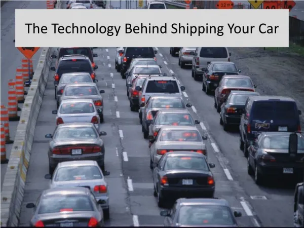
Download
1 / 32
320 likes | 331 Vues
SHIPPING TECHNOLOGY DEVELOPMENT. TOPIC 6. SHIPPING MAINTENANCE. Gas Tanker-LNG, LPG. All gas tankers, be it LNG, LPG fall into one of these categories of containment system and there are three options .

E N D
SHIPPING TECHNOLOGY DEVELOPMENT TOPIC 6
Gas Tanker-LNG, LPG All gas tankers, be it LNG, LPG fall into one of these categories of containment system and there are three options. • The first is to use a ‘self-supporting’ tank system, which sits on a cradle which separates it from the hull. • The second is the ‘membrane’ system which mouldsthe tank to the hull, which provides its strength, with insulation sandwiched between the tank membrane and the hull. The membrane must be able to cope with extreme temperature changes 3) The third option is the ‘prismatic’ system , which is a hybrid, using self-supporting tanks with an inner and outer skin, but tied into the main hull structure.
Gas Tanker-LNG, LPG • Although the design details vary enormously, the gas is liquefied onshore prior to loading and there are three ways to keep it liquid during transport:a) by pressure;b) by insulating the tanks; or by c) liquefying any gas which boils off and returning it to the cargo tanks (petroleum gas remains liquid at around −48∞C). • In the case of LNG tankers, there are a mix of petroleum gases such as propane, butane and isobutene and chemical gases such as ammonia, ethylene, propylene, butadiene and vinyl chloride. • Most of these gases liquefy at temperatures ranges from −0.5∞C to −50∞C , but some liquefy at much lower temperatures (e.g. ethylene at −103.9∞C). Gas tankers must be able to maintain gas at the required temperature during transport.
Gas Tanker-LNG, LPG • Broadly speaking,petrochemical gases are transported in semi-refrigerated or fully pressurized vessels under20,000 cubic meters, and LPG and ammonia gases are transported in fully refrigerated vessels, ranging in size from 20,000 cubic meters to 80,000 cubic meters, for long-haul, large-volume transportation. • Some semi-refrigerated vessels can carry ethylene (−104∞C) and ethane (−82∞C); and in a few cases LNG.
Nature of Liquid Cargo • In the case of LNG, it is a high-volume commodity and veryprice-sensitive, so the cost of transport plays a major part in the trade’s economics andship design. • LNG tankers generally form part of a carefully planned gas supply operation involving a substantial investment in shore-based liquefaction andregasification facilities. • The ship ranged in size up to 153,000 cubic meters, with a new generation of 270,000 cubic meters vesselsordered for the long-haul Middle East to USA trades, Malaysia to Japan, and South Korea .
Nature of Liquid Cargo…cont • Natural gas liquefies at −161.5∞C, at which temperature it is reduced to 1/630 times its original volume. • LNG tanker is a very sophisticated and expensive vessel, but the broad features are similar to the other tankers such as LPG. • The big difference is the engineering skills, materials and technology required to load, transport and discharge a liquid cargo at a temperature of −161.5∞C.
Analysis of Net Present Value Business Ventures in O&G Industry
PASSAGE PLANNING • APPRAISAL • PLANNING • EXECUTION • MONITORING
APPRAISAL • When you gather as much safety and navigation information to give you a safe voyage. • What type of information does this involve?The tides;Tidal streams;Under-keel allowances;Information from pilot books/sailing directions;Chart dangers (rocks, shallow water oil-rigs etc.);Traffic separation schemes;Weather information (shipping forecasts);Possible areas of restricted visibility;Any areas, which would involve an area of high traffic density.
Full coverage of up to date charts with details: • Currents – direction & rate of set; • Tides – times, heights and direction of rate of set; • Draught of ship during various stages; • Navigational lights and marks along the way; • Navigational warnings; • Climate data; • Ships maneuvering data. • Appraisal should indicate areas of danger and delineate areas of safe navigation for the ship.
PLANNING • Planning out the intended voyage, using all the information from Appraisal; • What have you to do to make a plan of your voyage?Plot the intended voyage making sure it is safe, and that the plan has been checked out by the master of the vessel, use way points, parallel indexing , courses, distance on each route, and by using all the information that you Appraised.
HOW ? • Plot on largest scale chart the intended track; • Mark all hazards and warnings prior to transfer to next chart; • Note safe speed and speed alterations that may be required; • Contingency plans, safe havens, use of bridge notebook.
EXECUTION • The master should find out how long his intended voyage should take, making sure he has enough water and fuel for the voyage; • He should take into account any weather conditions expected on the voyage; • Any areas of high traffic density that would make him deviate from his course (he should if possible make a plan to keep well clear of these areas).
CONSIDERATION • Reliability and condition of ships equipments; • ETA at critical points – course alterations, tide heights, pilot boarding etc.; • Meteorological conditions – visibility; • Day or night passage – accuracy of fix and threat of piracy; • Expected traffic conditions.
MONITORING • This is the act of checking your position often on a chart and that you remain in a safe distance from any danger areas (land); • Parallel Indexing should be used when you are alongside any hazards to maintain a safe distance; • Use all available means to ascertain the position and progress of the ship and that it is safe.
note • Human failure is a major cause of accident; • Passage planning cannot prevent this but may reduce its likelyhood; • Choice of route lies between the shortest, quickest or simplest way; • Berth to berth coverage must be properly planned; • No go areas – draft & danger areas; • Refer to publications on board.
THE IALA SYSTEM • IALA = International Association of Lighthouse Authorities is a non-profit organization founded in 1957 to collect and provide nautical expertise and advice . Function of Buoyage system (1976) • To harmonize aids to navigation worldwide • To ensure the movement of the vessels are safe • Expeditious and cost effectively • Protecting the environment
TYPE OF MARKS • The different types of marks used in the pilotage of vessels at sea are easily distinguished by their shape, colour, topmark by day and the colour and rhythm of the light by night. The five types of marks are: • Lateral Marks: indicate the edge of a channel • Cardinal Marks: indicate the position of a hazard and the direction of safe water • Isolated Danger Marks: indicate a hazard to shipping • Safe Water Marks: indicates the end of a channel and deep, safe water is ahead • Special Marks: indicate an area or feature such as speed restrictions or mooring area
LATERAL MARKS • Lateral marks define a channel and indicate the port and starboard sides of the navigation route to be followed into a waterway such as a harbour, river or estuary from seaward. The vessel should keep port marks to its left and keep starboard marks to its right. • The red colour for the left hand lateral signs were included in the region A. • the green colour for the left hand lateral signs were included in the region B. • the fairway direction is the one leading from the sea
SHAPE OF BUOYS • Can • Cone • Pillar • Spar
REGION A AND REGION B • System “A” all over the world, except “B” • System “B”= USA, Canada, Mexico, West Indies, Costa Rica, Panama, Guatemala, Surinam, Colombia, Venezuela, Peru, Brazil, Argentina, Paraguay, Chile, Japan, South Korea,Philippines.
In the Region A, duringthe day and night, the green colour is used to mark the right side of the fairway, and the red colour - to mark the left side (2+1 Flashing lights) : red and green In the Region B the colours are reversed, ie the red colour is used for the right side, and the green colour - for the left side(2+1 Flashing lights) :red and green
CARDINAL BUOYS • They are placed to the North, South, East or West from the hazard. • The cardinal buoys have mainly the shape of columns or poles. They are painted in horizontal, yellow and black stripes, and their topmarks (two cones) are painted black Function of Cardinal Buoys: • Indicate that the deepest water is an area on the named side of the mark • Indicate the safe side on which to pass a danger • Draw attention to a feature in a channel, such as a bend, junction, branch, or end of a shoal • Draw attention to a new danger such as a grounded ship. In such cases two equal marks are often placed together to indicate that it's a newly marked danger and is not yet printed in official charts.
Cardinal Buoys • white flashing light : quick (Q) or very quick (VQ) • 10 second for sequence flashing (very quick) • 15 second for sequence flashing (quick)
Special Marks • Special marks do not usually assist navigation but are used to indicate a feature such as recreation zones, • speed limits, mooring areas or cable and pipe lines including outfall sewerage pipes. Yellow flashing sequence Fl.(2) Safe Water Marks “Fairway Buoy” • indicate there is navigable water all around the mark including the end of a channel or mid • channel, however, this mark does not mark a danger. They are the only mark to have vertical stripes. • (L Fl 10s)
Isolated Danger Mark • to indicate a hazard to shipping such as a submerged rock or wreck which • has navigable water all around it. It is erected or moored above the hazard. • The double sphere topmark is an important feature and needs to be visible by day. The topmarks should be as large as possible with the spheres clearly separated. • distinctive sequence of flashing light consists of 2 quick flashes with intervals of 5 seconds