Download
1 / 24
240 likes | 335 Vues
University of Nevada – Reno Computer Science & Engineering Department Fall 2011 CPE 400 / 600 Computer Communication Networks. Lecture 25 Link Layer (Ethernet, Switch). slides are modified from J. Kurose & K. Ross. 5.1 Introduction and services 5.2 Error detection and correction

E N D
University of Nevada – Reno Computer Science & Engineering Department Fall 2011 CPE 400 / 600Computer Communication Networks Lecture 25 Link Layer (Ethernet, Switch) slides are modified from J. Kurose & K. Ross Introduction
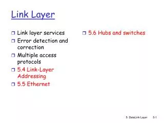
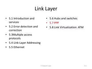
5.1 Introduction and services 5.2 Error detection and correction 5.3Multiple access protocols 5.4 Link-Layer Addressing 5.5 Ethernet 5.6 Link-layer switches 5.7 PPP 5.8 Link virtualization: MPLS 5.9 A day in the life of a web request Link Layer 5: DataLink Layer
Ethernet “dominant” wired LAN technology: • cheap $20 for NIC • first widely used LAN technology • simpler, cheaper than token LANs and ATM • kept up with speed race: 10 Mbps – 10 Gbps Metcalfe’s Ethernet sketch 5: DataLink Layer
Star topology • bus topology popular through mid 90s • all nodes in same collision domain • can collide with each other • today: star topology prevails • active switch in center • each “spoke” runs a (separate) Ethernet protocol • nodes do not collide with each other switch bus: coaxial cable star 5: DataLink Layer
Ethernet Frame Structure Sending adapter encapsulates IP datagram (or other network layer protocol packet) in Ethernet frame Preamble: • 7 bytes with pattern 10101010 followed by one byte with pattern 10101011 • used to synchronize receiver, sender clock rates 5: DataLink Layer
Ethernet Frame Structure (more) • Addresses: 6 bytes • if adapter receives frame with matching destination address, or with broadcast address (eg ARP packet), it passes data in frame to network layer protocol • otherwise, adapter discards frame • but node can be malicious to listen other conversations • Type: indicates higher layer protocol • mostly IP but others possible • e.g., Novell IPX, AppleTalk • CRC: checked at receiver, if error is detected, frame is dropped 5: DataLink Layer
Ethernet: Unreliable, connectionless • connectionless: No handshaking between sending and receiving NICs • unreliable: receiving NIC doesn’t send acks or nacks to sending NIC • stream of datagrams passed to network layer can have gaps • missing datagrams • gaps will be filled if app is using TCP • otherwise, app will see gaps • Ethernet’s MAC protocol: unslottedCSMA/CD 5: DataLink Layer
1. NIC receives datagram from network layer, creates frame 2. If NIC senses channel idle, starts frame transmission If NIC senses channel busy, waits until channel idle, then transmits 3. If NIC transmits entire frame without detecting another transmission, NIC is done with frame ! 4. If NIC detects another transmission while transmitting, aborts and sends jam signal 5. After aborting, NIC enters exponential backoff: after mth collision, NIC chooses K at random from {0,1,2,…,2m-1}. NIC waits K·512 bit times, returns to Step 2 Ethernet CSMA/CD algorithm 5: DataLink Layer
Jam Signal: make sure all other transmitters are aware of collision; 48 bits Bit time: .1 microsec for 10 Mbps Ethernet ;for K=1023, wait time is about 50 msec Exponential Backoff: Goal: adapt retransmission attempts to estimated current load heavy load: random wait will be longer first collision: choose K from {0,1}; delay is K· 512 bit transmission times after second collision: choose K from {0,1,2,3}… after ten collisions, choose K from {0,1,2,3,4,…,1023} Ethernet’s CSMA/CD (more) http://media.pearsoncmg.com/aw/aw_kurose_network_2/applets/csmacd/csmacd.html 5: DataLink Layer
CSMA/CD efficiency • Tprop = max prop delay between 2 nodes in LAN • ttrans = time to transmit max-size frame • efficiency goes to 1 • as tprop goes to 0 • as ttrans goes to infinity • better performance than ALOHA: and simple, cheap, decentralized! 5: DataLink Layer
application transport network link physical fiber physical layer copper (twister pair) physical layer 802.3 Ethernet Standards: Link & Physical Layers • many different Ethernet standards • common MAC protocol and frame format • different speeds: 2 Mbps, 10 Mbps, 100 Mbps, 1Gbps, 10G bps • different physical layer media: fiber, cable MAC protocol and frame format 100BASE-T2 100BASE-FX 100BASE-TX 100BASE-BX 100BASE-SX 100BASE-T4 5: DataLink Layer
Manchester encoding • used in 10BaseT • each bit has a transition • allows clocks in sending and receiving nodes to synchronize to each other • no need for a centralized, global clock among nodes! 5: DataLink Layer
5.1 Introduction and services 5.2 Error detection and correction 5.3 Multiple access protocols 5.4 Link-layer Addressing 5.5 Ethernet 5.6 Link-layer switches, LANs, VLANs 5.7 PPP 5.8 Link virtualization: MPLS 5.9 A day in the life of a web request Link Layer 5: DataLink Layer
twisted pair hub Hubs … physical-layer (“dumb”) repeaters: • bits coming in one link go out all other links at same rate • all nodes connected to hub can collide with one another • no frame buffering • no CSMA/CD at hub: host NICs detect collisions 5: DataLink Layer
Switch • link-layer device: smarter than hubs, take active role • store, forward Ethernet frames • examine incoming frame’s MAC address, selectively forward frame to one-or-more outgoing links when frame is to be forwarded on segment, uses CSMA/CD to access segment • transparent • hosts are unaware of presence of switches • plug-and-play, self-learning • switches do not need to be configured 5: DataLink Layer
Switch: allows multiple simultaneous transmissions A • hosts have dedicated, direct connection to switch • switches buffer packets • Ethernet protocol used on each incoming link, but no collisions; full duplex • each link is its own collision domain • switching:A-to-A’ and B-to-B’ simultaneously, without collisions • not possible with dumb hub C’ B 1 2 3 6 4 5 C B’ A’ switch with six interfaces (1,2,3,4,5,6) 5: DataLink Layer
Switch Table A • Q: how does switch know that A’ reachable via interface 4, B’ reachable via interface 5? • A: each switch has a switch table, each entry: • MAC address of host, interface to reach host, time stamp • looks like a routing table! • Q: how are entries created, maintained in switch table? • something like a routing protocol? C’ B 1 2 3 6 4 5 C B’ A’ switch with six interfaces (1,2,3,4,5,6) 5: DataLink Layer
Source: A Dest: A’ MAC addr interface TTL 60 1 A A A’ Switch: self-learning A • switchlearns which hosts can be reached through which interfaces • when frame received, switch “learns” location of sender: incoming LAN segment • records sender/location pair in switch table C’ B 1 2 3 6 4 5 C B’ A’ Switch table (initially empty) 5: DataLink Layer
Switch: frame filtering/forwarding When frame received: 1. record link associated with sending host 2. index switch table using MAC dest address 3. if entry found for destinationthen { if dest on segment from which frame arrivedthen drop the frame else forward the frame on interface indicated } else flood forward on all but the interface on which the frame arrived 5: DataLink Layer
Source: A Dest: A’ A’ A MAC addr interface TTL 60 60 1 4 A A’ A A’ A A’ A A’ A A’ A A’ A A’ Self-learning, forwarding: example A • frame destination unknown: C’ B 1 2 3 flood 6 4 5 • destination A location known: C selective send B’ A’ Switch table (initially empty) 5: DataLink Layer
S4 S3 S2 F I D H G E Interconnecting switches • switches can be connected together S1 A C B • Q: sending from A to G - how does S1 know to forward frame destined to F via S4 and S3? • A: self learning! • works exactly the same as in single-switch case! 5: DataLink Layer
Self-learning multi-switch example Suppose C sends frame to I, I responds to C S4 1 S1 2 S3 S2 A F I D C B H G E • Q: show switch tables and packet forwarding in S1, S2, S3, S4 5: DataLink Layer
Institutional network mail server to external network web server router IP subnet 5: DataLink Layer
Switches vs. Routers • both store-and-forward devices • routers: network layer devices • examine network layer headers • switches are link layer devices • routers maintain routing tables, implement routing algorithms • switches maintain switch tables, implement filtering, learning algorithms 5: DataLink Layer