Download
1 / 16
190 likes | 635 Vues
COMMUNICATION SYSTEM EECB353 Chapter 3 Part I ANGLE MODULATION. Dept of Electrical Engineering Universiti Tenaga Nasional. Introduction. Amplitude Modulation (AM) – Amplitude of the carrier varies accordingly to the message signal.

E N D
COMMUNICATION SYSTEM EECB353Chapter 3 Part IANGLE MODULATION Dept of Electrical Engineering Universiti Tenaga Nasional
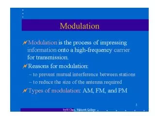
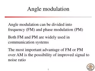
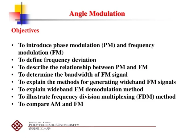
Introduction • Amplitude Modulation (AM) – Amplitude of the carrier varies accordingly to the message signal. • Angle Modulation (FM and PM) – Angle of the carrier varies accordingly to the message signal while amplitude of the carrier is constant. where m(t) = angle modulated waveform Vc = peak carrier amplitude c = carrier radian frequency (=2fc) (t) = instantaneous phase deviation (radians) (1)
Introduction • Angle modulation as a function of modulating signal can be expressed mathematically as (t) = F [vm(t)] (2) where vm(t) = Vmsin(mt) Vm = peak modulating signal amplitude m = modulating signal radian frequency (=2fm) Figure: Angle modulation vs amplitude modulation
Introduction • Whenever the frequency of a carrier varied, the phase is also varied and vice versa. • Thus, FM and PM must both occur whenever either form of angle modulation is performed. • If the freq of the carrier is varied directly in accordance with the modulating signal, FM results. • If the phase of the carrier is varied directly in accordance with the modulating signal, PM results. • Therefore, direct FM is indirect PM and direct PM is indirect FM. • DirectFM/PM – frequency/phaseof the constant amplitude carrier is varied proportionally to the amplitude of the modulating signal at a rate equal to the frequency of the modulating signal.
Introduction • How carrier freq, fc change in accordance to modulating signal vm(t)? • +ve increase in modulating signal amplitude causes increase in carrier freq. • Deacrease (or –ve increase) in modulating signal amplitude causes decrease in carrier freq. Figure: Angle modulated wave in frequency domain
Mathematical Analysis Instantaneous phase deviation = = (3) Instantaneous frequency deviation = = (4) where Kpand Kf are constant (deviation sensitivity of phase and freq) • For a modulating signal, • Phase modulation, (5) • Frequency modulation, (6)
Carrier Modulating signal FM PM Figure : Phase and Frequency Modulation of sinusoidal carrier by a single-freq modulatingsignal.
PM The phase deviation of modulator o/p is prop. to m(t). The freq deviation is prop. to the derivative of the phase deviation, thus the i is max when the slope of m(t) is max and min when the slope of m(t) is min FM Freq. deviation is prop. to m(t), thus the i is max when the m(t) is max and min when m(t) is min Note that m(t) is not shown along with the modulator o/p. It would not be possible to distinguish the PM and FM o/p Accos 2fct PM FM Output of PM and FM modulators for a sinusoidal, Accos 2fct
Comparison of PM and FM modulator outputs for a unit-step input. (a) Message signal. (b) Unmodulated carrier. (c) Phase modulator output (kp = ½). (d) Frequency modulator output. PM i =fc for t<t0 and t>t0 The phase of unmodulated carrier is advanced by kp=/2 rads for t>t0 giving rise to a signal that is discontinues at t=t0 FM i =fc for t<t0 and, = fc+ fdfor t>t0 The modulator o/p phase is, however, continues at t=t0
Mathematical Analysis • For FM – maximum freq deviation (change in the carrier freq) occurs during the maximum +ve and –ve peaks of the modulating signal i.e freq deviation to the amplitude of the modulating signal. • For PM – maximum freq deviation occurs during zero crossings of the modulating signal i.e freq deviation to the slope or first derivative of modulating signal. • For FM and PM – rate of freq change is equal to the modulating signal freq. • Example : A transmitter operates on a frequency of 915 MHz. The maximum FM deviation is +/- 12.5 kHz. What are the maximum and minimum frequencies that occur during modulation? • Example : A phase modulator has Kp= 2 rad/V. What voltage of sinewave would cause a peak phase deviation of 60 degrees ?
Phase Deviation and Modulation Index, m Kf = deviation sensitivity for frequency Kp = deviation sensitivity for phase m = modulation index and peak phase deviation, ∆Ѳ rad
Frequency Deviation and Percent Modulation • Frequency Deviation – the change in frequency that occurs in the carrier when it is acted on by a modulating-signal frequency. • Typically given as a peak frequency shift in hertz (f). • The peak-to-peak freq deviation (2f) is called carrier swing. • For FM, the deviation sensitivity, Kf is often given in hertz/volt. Thus, the peak freq deviation can be expressed mathematically as:
Frequency Deviation and Percent Modulation • With PM, modulation index and peak phase deviation are directly proportional to the amplitude of the modulating signal and unaffected by its frequency. • With FM, both modulation index and freq deviation are directly proportional to the amplitude of the modulating signal, and modulation index is inversely proportional to its freq. • Percent Modulation – the ratio of actual freq deviation to the maximum freq deviation allowed in percentage form. % modulation = (27)
Examples • Determine the peak frequency deviation (f) and modulation index (m) for an FM modulator with a deviation sensitivity, Kf = 5kHz/V and a modulating signal vm(t) = 2 cos(22000t). • Determine the peak phase deviation (m) for a PM modulator with a deviation sensitivity Kp = 2.5rad/V and a modulating signal vm(t) = 2 cos(22000t). • Below is the angle modulated signal produced after FM modulator; Determine: • Modulation index • Peak frequency deviation
Examples 4. For a direct FM modulation, an information signal, is used to modulate a carrier, . For a deviation sensitivity of 2.5rad/s/V, calculate • The peak frequency deviation in Hz • The modulation index • The percent modulation for maximum frequency deviation of 75kHz • Using part (b), the deviation sensitivity for the indirect PM • The carrier swing • Write out the mathematical expression of the FM wave