Download
1 / 28
280 likes | 606 Vues
BOC1 Run Thru: Agenda 14h30 Start CB Local Meeting 16h00 Break for Tea 16h30 Start Telephone Conference 18h00 Conclusions 18h30 Finish BOC1 Run Thru: Outline What BOC Does Provides the interface between ROD and Detector Modules Provides the interface between ROD and ROBs

E N D
BOC1 Run Thru: Agenda • 14h30 Start CB Local Meeting • 16h00 Break for Tea • 16h30 Start Telephone Conference • 18h00 Conclusions • 18h30 Finish
BOC1 Run Thru: Outline What BOC Does • Provides the interface between ROD and Detector Modules • Provides the interface between ROD and ROBs • Receives Clock from TIM via backplane, provides copy for ROD. • Also provides ancillary timing functions
BOC1 Run Thru: Outline • ROD <-> Module interface: • Clock and Command streams to modules • clock-control encoding and timing trims • electrical to fibre-optic conversion • Data streams from modules • fibre-optic to electrical conversion • data sync and timing functions • ROD <-> ROB interface: • Electrical to Opto with error detection and correction plus flow control
BOC1 Run Thru: BOC0 • BOC0 was the proof-of-principle board • Full scale (48 command, 96 data streams) • Available components (opto & ASICs) • BPM4 & Current Mirrors & Quad VCSELs • Test bench for some circuits • Full functionality • (inc. Some Pixel 80MHz streams)
BOC1 Run Thru: . BOC-RIG • Provides VME access to BOC via Set-Up Bus - @ front of crate in place of ROD • allows SLOG to drive all 48 command streams (fanned out from 12) • selects 12 of the 96 data streams for Mustard • Provides specialised test facilities: • SNAPshot of the 12 selected streams • SCOPE MODE • generation of 80MHz Pixel test data
BOC1 Run Thru: . BOC-RIG v2 • Does all v1 does • provides 12 un-encoded command streams in optical form to give 12 SLOG-derived opto signals for BOC data stream testing. • The 80MHz Pixel data mode should work for 6 of these streams • Board Manufactured, but not fully tested • BOC-RIGs key to BOC1 testing
BOC0 Test Results: . Set-Up Bus • Set-Up Bus operations work fine: • read and write to BOC registers generally OK • Manufacturer # top bit sometimes wrong: hole in ROD or BOC logic code .. Fix very unlikely to need schematic change • write to BPM4 registers OK (BPM4 read-back known not to work) • write to laser current DACs OK (serial path) • write to data threshold DACs OK (serial path) • write to data delay chips OK (I2C path) • write to clock delay (fine and coarse) OK • write to clock control ccts OK … but will change
BOC0 Test Results: . Data Streams • Wrong pin-out for PIN array means streams reach ROD in wrong order • not worth fixing on BOC0 .. • simply fixed on BOC1 • The eye-pattern looks very good: • threshold scans not completely clean: probably due to laser deficiences • delay scans show timing jitter on looped-back data of well less than 1ns • The Streams implemented in CPLDs OK • De-Muxing from 80MS/s to 40MS/s is good
BOC0 Testing: Yet To Do: • Check the S-Link: • S-Link components still not complete (awaiting the ODIN Link Source Card) • Controlling modules ? • Slow command data from modules? • .. Eg. Front-end registers • Data from Modules ? .. real and calibration • System set-up operations: • designing and refining procedures • are the provisions good enough?
BOC1 Run Thru: BOC1 • BOC1 is the pre-production prototype: • using production compatible components • should move seamlessly into production
BOC1 : Differences • A (remarkably small) number of PCB fixes • Reduce PCB depth to 220mm (was 240mm) • Add Power Monitor and Power-up Reset • Clock Circuit changes: • fail-safe provision (PLL?) • implement a couple of BOC0 patched mod’s • double range of fine clock delay to 5ns • reduce short-term jitter • guarantee mark-space • Move to New Opto and ASICs: see next slide • Improve laser interlock provision
BOC1 : . New Opto .. Details • BPM12 is major rework of BPM4: • 12 streams rather than 4 • drives common cathode lasers • many other improvements • New Plug-In Opto Modules by Academica Sinica of Taiwan: • 4 x OpTX .. BPM12, VCSEL12 & 2x MDACs (Laser Current) • 8 x OpRX .. DRX12, PIN12 & 2x MDACs (Threshold) • size: 21x30mm • each OpTX replaces 3x BPM4s, 3x Mitel VCSEL4s, 12 current mirrors & 1.5 MDACs • each OpTX replaces 1x DRX12, 1x Mitel PIN12 & 1.5 MDACs • MultiDAC mapping more difficult: • changes to control circuitry
BOC1 Run Thru: . New Opto Academica Sinica OpRX Prototype
Interlocks BOC1 Run Thru: . Block Diag. Unchanged! With Optional 80MS/s - 2x40MS/s De-Muxing
BOC1 Run Thru. . BOC0 Layout Laser Current - DACs+Amps VCSEL arrays Current Mirrors Clock Circuits BPMs S-Link Source Card Pixel Compatible Streams T/Hold DACs Data Delay Chips DRX amp/discrim Data Registers PIN arrays
BOC1 Run Thru. . BOC1 Layout Command Stream CMOS Buffers OpTX Plug-Ins S-Link Source Card Commands from ROD Events from ROD Set-Up Bus from ROD OpRX Plug-Ins Clock Circuits Data Stream CPLDs (80MS/s - 40MS/s De-Mux capable) Data Delay Chips Clock From TIM Data to ROD LVDS Receivers
BOC1 Run Thru: . BOC0 v BOC1 Layout Clock and Command Section BOC0 Ctrl CPLD S-Link Section Clock Section Data RX Section
BOC1 Run Thru: . PIXEL Working PIXEL BOC .. Layers B and 1
BOC1 Run Thru: . PIXEL Working PIXEL BOC .. Layers 2 and Disk
I/P (80MS/s) BOC1 Run Thru: . PIXEL Working PIXEL BOC .. 80MS/s - 2x 40MS/s De-Muxing Data Delay 0-24ns
BOC1 Run Thru: . PIXEL Working PIXEL BOC .. 80MS/s - 2x 40MS/s De-Muxing
BOC1 Run Thru: . PIXEL Working PIXEL BOC .. 80MS/s - 2x 40MS/s De-Muxing
BOC1 Run Thru: . Schematics The Full set of BOC1 Schematics can be found in BOC1_Drgs.pdf • Sheet 1: • J2 & J3 Connections • Power Monitors • VPIN regulator for PIN Bias Voltage • Sheet 2: • Clock Generation Circuitry and Fan-Out • Sheet 3: • Control CPLD • Fallback Crystal Oscillator • Interlock Circuits • Indicator LEDs • Sheet 4: • Set-Up Bus Buffering • CMOS Buffers for BPM Control Signals • S-Link Wiring • Shadow RAM for Readback of Serial Data • Sheets 5-6: Clock and Command • OpTX Module Connections and Buffering • Sheets 7-10: Data Receiver Streams • OpRX Modules • LVDS Data Receivers • PHOS4 Data Delay chips • Data Stream CPLDs • LVDS Clock Receivers • Sheet 11: • MultiDAC Control • CPLD In-System Programming Connectors • Sheet 12: • Data Stream Buffers for ROD Interface
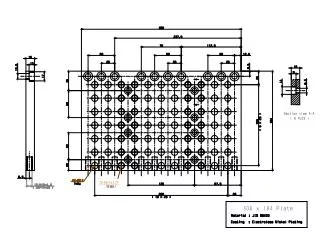
BOC1 Run Thru: . Layout
BOC1 Run Thru: . Layout
BOC1 Run Thru: . Clock Detail
BOC1 Run Thru: . Clock & Command
BOC1 Run Thru: . Data RX Section