Download
1 / 44
440 likes | 619 Vues
EET 2261 Unit 13 Controlling Stepper Motors and Servos. Read. Homework #13 and Lab #13 due next week. Final Exam next week. Stepper Motors and Servos. There are many kinds of electric motors. (See Wikipedia article .)

E N D
EET 2261 Unit 13Controlling Stepper Motors and Servos • Read. • Homework #13 and Lab #13 due next week. • Final Exam next week.
Stepper Motors and Servos • There are many kinds of electric motors. (See Wikipedia article.) • In many motors, the rotor spins continuously, with no way of precisely controlling the motor’s rotational position and speed. • Stepper motors and servos are two widely used kinds of motors whose position and speed can be precisely controlled.
Coverage of Motors in the Textbook • Our textbook does not discuss stepper motors or servos (except in Question 7 on page 200). • But Section 21 discusses pulse width modulation (PWM), which is the technique used to control servos.
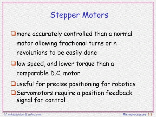
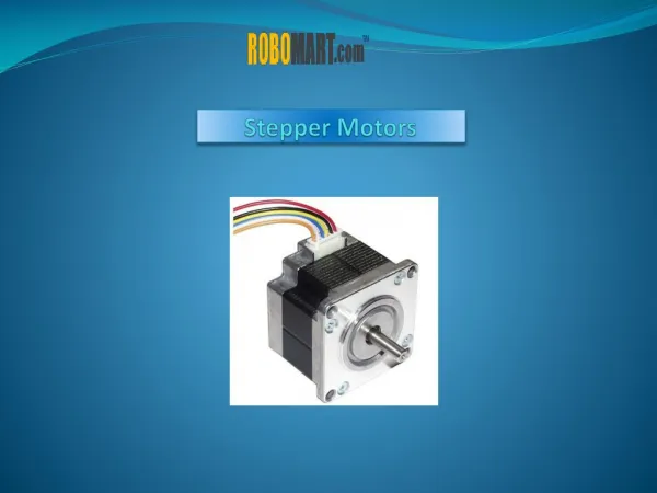
Stepper Motors • A stepper motor is a digitally controlled motor that allows precise control over the position of the motor’s rotor. • Changes in the digital input rotate the motor’s rotor by a precise amount, which is called a step or step angle. • Depending on the motor, this step angle may be as small as 1 (or less) or as large as 45. • On our motors, the step angle is 3.6.
Electromagnets • Recall that an electromagnet behaves like a magnet only when current is passing through it. It’s a magnet that you can “turn on” or “turn off.” • Electromagnets are constructed by wrapping wire around an iron-alloy bar. (Illustration from Wikipedia.)
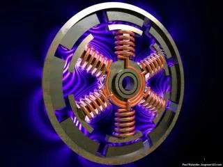
Magnets in a Stepper Motor • A stepper motor has a permanent magnet connected to its rotor and electromagnets connected to its stator. • The digital signals controlling the motor turn the electromagnets on and off in sequence, which results in rotation of the rotor. Simplified image from John Iovine’sPIC Microcontroller Project Book, 2nd ed.
Rotating a Stepper Motor (Simplified Picture) In this example, how big is each step? From John Iovine’sPIC Microcontroller Project Book, 2nd ed.
Half-Stepping • In the previous illustration, only one of the electromagnets was on at a time. • We can get finer resolution by sometimes turning on two electromagnets at a time. This technique is called half-stepping.
Types of Stepper Motors • Different designs result in several types of stepper motors: • Unipolar • Bipolar • Universal (which combine characteristics of unipolar and bipolar motors) • Our motor is a unipolar stepper motor.
Wiring a Stepper Motor • The number of wires on a stepper motor varies, depending on the motor’s type. • Bipolar Stepper Motor: 4 wires • Unipolar Stepper Motor: 5 or 6 wires • Universal Stepper Motor: 8 wires
Online Tutorial • The website at http://homepage.cs.uiowa.edu/~jones/step/ contains an excellent online tutorial on stepper motors, including this animation showing the operation of a unipolar motor.
Our Stepper Motor • Our motor is made by Howard Ind., part number 1-19-4202. • As shown on its specifications sheet, it’s a unipolar motor with a 3.6 step angle.
Interfacing Problems • Two interfacing problems arise when driving a motor from a digital system: • Motors introduce a great deal of electrical “noise” into a system. This noise can disrupt the operation of sensitive digital circuits such as the HCS12. • Motors consume more current than most digital outputs can supply. Therefore we can’t connect the motor directly to the HCS12’s output pins.
Solution to Interfacing Problem #1 (Noise) • Use separate power supplies, one for the motor and one for the HCS12. • If needed, we could also use an optoisolator, such as the ILQ74, to provide further isolation between the HCS12 and the motor. • We’ll power our motor from the 9 V pin in the Dragon12 board’s lower left corner. For this to work, we must plug in the Dragon12’s power adapter, instead of just powering the board from its USB port.
Solution to Interfacing Problem #2 (Supplying Adequate Current) • Use one of the following circuits between the HCS12 and the motor: • Power transistors, such as the TIP120. • Motor driver IC, such as the ULN2003 or the TB6612FNG H-bridge. The Dragon12 board has a TB6612FNG (U12 near the board’s lower left corner).
Toshiba TB6612FNG • This chip contains a popular driver design called an H-bridge. It is often used to control DC motors and stepper motors. • TB6612FNG datasheet.
Connections to TB6612FNG • On the Dragon12 board, the TB6612FNG is connected to Ports B and P of the HCS12. • Figure from Dragon12 Schematic Diagram 5.
Code for Turning a Stepper Motor • Once you’ve made the proper connections and configured the HCS12’s ports, stepper motors are easy to program. The following code will turn our motor counterclockwise (CCW):
Servos • A servo motor (or servo) is a package containing a DC motor connected via gears to a shaft. • It also contains a feedback circuit that precisely controls the shaft’s angle of rotation. • Unlike a motor whose rotor spins continuously, a servo is usually used to set the shaft to a specific angle of rotation and then hold it there for a while.
Servos in RC Vehicles • Servos are commonly used in small robotics and in radio-controlled (RC) airplanes, cars, and boats. • In an RC airplane, for example, servos may control the plane’s throttle, rudder, elevators, ailerons, landing gear, etc. • Next slide shows inner workings of an RC airplane.
Servo: Block Diagram • Diagram above demonstrates feedback, in which a system’s output is fed back in as an input to provide more accurate control over the output. • Feedback is a fundamental concept in most control systems.
Wiring a Servo • Servos have three wires: • Power (red) • Ground (black) • Control signal (yellow or white)
Connecting Servos to the Dragon12 • The Dragon12 board has four connectors (near the center of the top edge) for servos, labeled PP4, PP5, PP6, PP7. • Jumper J35 lets you choose whether to power the servo from the board or from an external supply. We’ll power it from the board, but to do so we must have the power adapter plugged in.
Dragon12 Connections • On the Dragon12 board, the servo outputs are connected to Port P of the HCS12. • Figure from Dragon12 Schematic Diagram 5.
Our Servo • Our servo is made by Hitec, part number HS-311. • See ServoCity’s webpage for detailed specifications.
Controlling a Servo • The servo’s control signal is a 50 Hz pulse train. Therefore, what is this signal’s period? • As shown on the next slide, the width of the pulse is crucial in controlling the servo.
Controlling a Servo • The control signal’s pulse width determines the shaft’s angle of rotation. • Typically this pulse width ranges from about 0.5 ms to about 2.5 ms, interpreted as follows: • 1.5 ms pulse width: 0 rotation. • Pulse width less than 1.5 ms: rotate counterclockwise (up to 90, for our servo). • Pulse width greater than 1.5 ms: rotate clockwise (up to 90).
Pulse Width Modulation • The term pulse width modulation (PWM) refers to the technique of varying a signal’s pulse width to control a device such as a servo. (PWM is use to control other kinds of devices, too, including DC motors.)
PWM Using the HCS12 • One way to perform PWM using the HCS12 would be to write a loop that sets an output pin HIGH and LOW at the right times to generate pulses of the desired width and frequency. • This approach would tie up a lot of the CPU’s time. • A more efficient way is to use the HCS12’s built-in PWM block. Using this approach, once we have configured the PWM block correctly, it will generate pulses of the desired width and frequency without tying up the CPU.
Pulse Width Modulation (PWM) Block • The Pulse Width Modulation (PWM) block shares pins with general-purpose I/O Port P. • Figure from p. 6 of textbook or page 23 of Device User Guide).
Block Diagram of Pulse Width Modulation (PWM) Block • The PWM block’s eight channels let us generate up to eight different PWM signals at the same time. • See page 14 of the PWM_8B8C Block User Guide.
Special-Function Registers Associated with the PWM Block • The 39 special-function registers located at addresses $00A0 to $00C7 let us control the operation of the PWM block. • See page 35 of Device User Guide.
Special-Function Registers That We’ll Use • The following registers are the most important ones for using the PWM block: • PWM Enable Register (PWME) • PWM Polarity Register (PWMPOL) • PWM Prescale Clock Select Register (PWMPRCLK) • PWM Scale A Register (PWMSCLA) • PWM Clock Select Register (PWMCLK) • PWM Channel Period Registers (PWMPERx): one register for each of the eight channels • PWM Channel Duty Registers (PWMDTYx): one register for each of the eight channels
PWM Enable Register (PWME) • The bits in this register let us enable or disable each of the eight PWM channels. If we enable a particular channel, then its I/O pin cannot also be used for general-purpose I/O as part of Port P. • Figure from p. 19 of PWM_8B8C Block User Guide.
PWM Polarity Register (PWMPOL) • For each PWM channel, we can choose whether the PWM signal starts HIGH and then goes LOW in each cycle, or vice versa. • Figure from p. 20 of PWM_8B8C Block User Guide.
PWM Clocks • The PWM block has four clocks that are derived from the system’s bus clock: • Clock A • Clock B • Clock SA (Scaled A) • Clock SB (Scaled B) • PWM Channels 0, 1, 4, 5 can use either Clock A or Clock SA • PWM Channels 2, 3, 6, 7 can use either Clock B or Clock SB. • The next three slides discuss the registers that control these clocks.
PWM Prescale Clock Select Register (PWMPRCLK) • The bits in this register set the frequencies of Clock A and Clock B, as follows: Figures from p. 23 of PWM_8B8C Block User Guide.
PWM Scale A Register (PWMSCLA) • The 8-bit value in this register sets Clock SA’s frequency, according to the formula: • Figures from p. 28 of PWM_8B8C Block User Guide.
PWM Clock Select Register (PWMCLK) • Each PWM channel has one bit in this register to select which clock it uses: • For PWM Channels 0, 1, 4, 5, we can choose between Clock A and Clock SA. • For PWMM Channels 2, 3, 6, 7, we can choose between Clock B and Clock SB. • Figure from p. 22 of PWM_8B8C Block User Guide.
PWM Channel Period Registers (PWMPERx) • Each PWM channel has one of these registers. • The value in this register determines the period (cycle time) of the signal generated by the PWM channel: • Signal period = PWMPERx × Period of selected clock source • Figure from p. 31 of PWM_8B8C Block User Guide.
PWM Channel Duty Registers (PWMDTYx) • Each PWM channel has one of these registers. • Assuming PWMPOL has been set so that the signal starts HIGH, the value in this register determines the pulse width (time high) of the signal generated by the PWM channel: • Pulse width = PWMDTYx × Period of selected clock source • Figure from p. 32 of PWM_8B8C Block User Guide.
Sample Code for Configuring PWM Channel 4 • Note that code is incomplete: you must decide what values to load into PWMPER4 and PWMDTY4.