Download
1 / 11
150 likes | 529 Vues
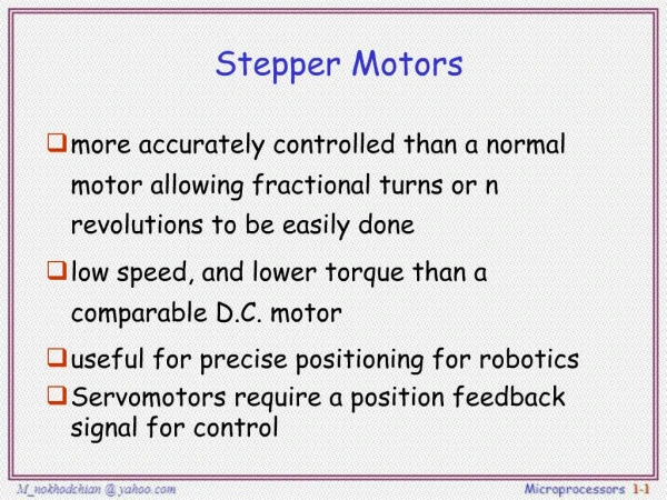
Chapter 19: Stepper Motors. Introduction. Stepper motors are special motors that are used when motion and position have to be precisely controlled. Stepper motor operates in discrete steps.

E N D
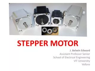
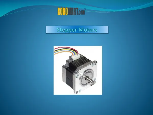
Chapter 19:Stepper Motors Electro Mechanical System
Introduction • Stepper motors are special motors that are used when motion and position have to be precisely controlled. • Stepper motor operates in discrete steps. • Depending on the design the stepper motor can be advanced by 90o, 45o, 18o or as little as fraction of a degree per pulse. • Stepper motor can turn clockwise or counter-clockwise, depending on the sequence of pulses that are applied to the windings. • The pulses are counted and stored , clockwise pulses cw (+) and counter-clockwise ccw (-). • As a result the net number of steps are known all the times. Electro Mechanical System
Elementary stepper motor • Simple stepper motor consists of stator having three salient poles and a two poles rotor. The windings can be connected to a dc power supply with the help of three switches A,B,C. • When switches are open the rotor can take up any position. • However when switch A is closed, the resulting magnetic field created by pole 1 will attract the rotor and it will line up. • Open switch A and simultaneously close switch B, the rotor will rotate 60o cw and will line up with pole 2. Open B and close C, the rotor will rotate 60o cw and will line up with pole 3. Electro Mechanical System
Elementary stepper motor • We can make the rotor advance 60o ccw by closing and opening the switches in the sequence A,B,C,A,B,C……. and reverse the direction with sequence A,C,B,A,C……. • In order to fix the final position of the rotor, the last switch must remain closed. • The motor will remain locked in this state, provided external torque applied does not exceed the holding torque. Electro Mechanical System
Effect of Inertia • The motor operates at no load, at the moment switch A is opened and B is closed, the motor will accelerating towards pole 2. It rapidly picks up speed and soon reaches center of pole 2, where it should come to rest. • Since the motor is running at considerable speed and it will overshoot the center line. • As soon as it pass pole 2, the field of pole 2 will pull it in the opposite direction, thereby braking the rotor. The rotor will come to halt and start moving in the opposite direction. • The rotor will therefore oscillate like a pendulum around the center of pole 2. • The oscillation will gradually die out due to frictions. Electro Mechanical System
Effect of Inertia • Following diagram shows the angular position of the rotor as a function of time. The rotor starts at 0o (Center of pole 1) and reaches 60o (Center of pole 2) after 2 ms. It overshoots center line by 30o before coming to halt at 3 ms. The rotor now moves in the reverse and crosses the center line again at 4 ms. • The oscillation will gradually stop when t > 10ms. • The speed is momentarily zero at t = 3ms, 5ms, 7ms and becomes permanently zero at t >10ms. Electro Mechanical System
Effect of Inertia • Without making any other changes if we increase the inertia, by mounting flywheel on the shaft. • We discover that both oscillation and amplitude increases with increase in inertia. The rotor also takes more time 20 ms instead on 10 ms to settle down. Electro Mechanical System
Effect of Inertia • The oscillation can be damped by increasing the friction. For example if we increase the bearing friction, the oscillation can be suppressed. • In practice we usually use viscous fluid such as oil, it is also known as viscous damper. Electro Mechanical System
Effect of mechanical load • Let the rotor is coupled to mechanical load. Will take longer for to attain 60o position from 4ms instead of 2 ms without load. • The overshoot is smaller and the oscillations are damped quickly. • Both mechanical load and inertia increase the stepping time. • For faster stepping response, the inertia of the motor and its load should be kept as small as possible and the oscillation should be damped using a viscous damper. • The time can also be reduced by increasing the current in the winding. However there is limitation to increase in current. Electro Mechanical System
Torque versus speed curve • The torque developed by the stepper motr depends upon the current. • Graph shows relationship between torque and current in a typical stepper motor. • At a rated pulse current of 8 A, the motor develops a torque of 3 N.m. • This is the torque that the motor can exert while moving from one position to another. • It is called pull-over torque. Electro Mechanical System
Start-Stop stepping rate • In star-stop fashion, there is upper limit to a stepping rate • For too fast pulse rate, motor is unable to follow & will loose steps • For synchronism, the rotor must settle before advancing • Interval between two steps is at lease 6 ms, so the stepping rate is limited to a 1000/6 = 167 steps per second (sps) • We also know that higher the load and greater the inertia, the lower will be the allowable number of steps per second • The start-stop stepping mode is also called start without error mode Electro Mechanical System