Download

1 / 16
180 likes | 246 Vues
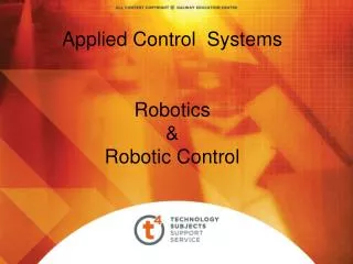
Applied Control Systems Stepper Motors. Stepper Motor / Electro magnet. Outside Casing. Stator. Rotor. Internal components of a Stepper Motor. Rotor. Stator. Coils. Cross Section of a Stepper Motor. Stators. Rotor. Full Step Operation. Four Steps per revolution i.e. 90 deg. steps.

E N D
Applied Control Systems • Stepper Motors
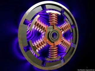
Outside Casing Stator Rotor Internal components of a Stepper Motor Rotor Stator Coils
Cross Section of a Stepper Motor Stators Rotor
Full Step Operation Four Steps per revolution i.e. 90 deg. steps.
Half Step Operation Eight steps per. revolution i.e. 45 deg. steps.
Winding number 1 One step 6 pole rotor Winding number 2
Six pole rotor, two electro magnets. How many steps are required for one complete revolution?
The top electromagnet (1) is turned off, and the right electromagnet (2) is energized, pulling the nearest teeth slightly to the right. This results in a rotation of 3.6° in this example. Practical Stepper motor operation The top electromagnet (1) is turned on, attracting the nearest teeth of a gear-shaped iron rotor. With the teeth aligned to electromagnet 1, they will be slightly offset from electromagnet 2
The left electromagnet (4) is enabled, rotating again by 3.6°. When the top electromagnet (1) is again enabled, the teeth in the sprocket will have rotated by one tooth position; since there are 25 teeth, it will take 100 steps to make a full rotation in this example. The bottom electromagnet (3) is energized; another 3.6° rotation occurs.
Stepper motor applications Stepping Motor to move read-write head
Stepper motor applications Paper feeder on printers Stepper motors CNC lathes
Stator coils Rotor CNC Stepping Motor
Advantages / Disadvantages Advantages:- Low cost for control achieved Ruggedness Simplicity of construction Can operate in an open loop control system Low maintenance Less likely to stall or slip Will work in any environment Disadvantages:- Require a dedicated control circuit Use more current than D.C. motors High torque output achieved at low speeds
Servo Motor Detail Actuator Reduction gear Position feedback Potentiometer (closed loop system) + 5V Small electric DC motor