Download

1 / 40
1.39k likes | 4.02k Vues
Distillation V Multicomponent Distillation. Mass Transfer for 4 th Year Chemical Engineering Department Faculty of Engineering Cairo University. √. √. √. √. Introduction. KEY COMPONENTS.

E N D
Distillation VMulticomponent Distillation Mass Transfer for 4th Year Chemical Engineering Department Faculty of Engineering Cairo University
√ √ √ √
KEY COMPONENTS The solution in some methods is based on choice of two “key” components between which it’s desired to make the separation: “Light Key (LK)” and “Heavy Key (HK)”. • Light Key: is the component that is desired to be kept out of the bottom product. • Heavy Key: is the component that is desired to be kept out of the top product. Concentrations of the key components in the top and bottom products must be specified. All other components except light and heavy keys are called the non-keys components. a
Logically ... In the case shown: Heavy Key (HK):C7 Light Key (LK):C6 The solution in some methods is based on the fact that if the light key is eliminated (nearly or completely) from bottom product then OF COURSE theheaviercomponents will be also eliminated from bottom product. And the same for the heavy key.
1- Lewis Matheson Method • Similar to Lewis method we used in binary system. • Tray to tray calculations are done with the assumption of constant molar flow rates of liquid and vapour in each section. • First Calculate L, V, L’, V’ (How?) • Top section tray to tray calculations are done till xi≤xFi • Bottom section tray to tray calculations are done till y ≥xFi
1- Lewis Matheson Method For Top Section: If total condenser y1i=xoi=xDi Equilibrium relation: x1i=y1i/Ki Operating line: V.y2i=L.x1i + D.xDi
1- Lewis Matheson Method For Bottom Section: First: Reboiler (m=0): Equilibrium relation: yri=KixWi Operating line: L’.x’1i=V’.y’ri +W.xWi
1- Lewis Matheson Method For Bottom Section: For m=1: Equilibrium relation: y1i=Kix1i Operating line: L’.x’2i=V’.y’1i +W.xWi
1- Lewis Matheson Method NOTE: To do these calculations we must know the value of “K” K=f(T,P) Operating pressure is known BUT operating temperature varies from tray to another, so each tray calculation will be done by assuming T and checking it from Sx or Sy (as if it’s a normal flashing problem)
1) A distillation column is designed for light gases fractionation operates at a reflux ratio of 2.5, if the condenser temperature is 60oC and it’s required to get a top product of the following specs: The temperature of the first plate is 65oC and that of the second plate is 70oC, the data for K values for the components are as follows: Estimate the composition of vapour and liquid leaving the second stage.
V=(R+1)D=3.5*45.1=157.85 mol/sec L=RD=2.5*45.1=112.75 mol/sec Since x1 and y1 left the first stage and total condenser (y1i=xDi=xoi) x1i=y1i/Ki xC3)1=0.111/2.36=0.047 xi-C4)1=0.333/1.19=0.279 xn-C4)1=0.532/0.86=0.619 xi-C5)1=0.022/0.42=0.053 xn-C5)1=0.002/0.32=0.007
Do material balance for the loop: VyC3)2=LxC3)1+DxC3)D Vyi-C4)2=Lxi-C4)1+Dxi-C4)D Vyn-C4)2=Lxn-C4)1+Dxn-C4)D Vyi-C5)2=Lxi-C5)1+Dxi-C5)D Vyn-C5)2=Lxn-C5)1+Dxn-C5)D Substitue: 157.85*yC3)2=112.75*0.047+5 157.85*yi-C4)2=112.75*0.279+15 157.85*yn-C4)2=112.75*0.619+24 157.85*yi-C5)2=112.75*0.053+1 157.85*yn-C5)2=112.75*0.007+0.1 yC3)2=0.0652 yi-C4)2=0.2943 yn-C4)2=0.5942 yi-C5)2=0.0442 yn-C5)2=0.0056
Since x2and y1left the second stage x2i=y2i/Ki xC3)2=0.0652/2.58=0.0253 xi-C4)2=0.2943/1.37=0.2148 xn-C4)2=0.5942/0.9=0.6602 xi-C5)2=0.0442/0.51=0.0867 xn-C5)2=0.0056/0.4=0.0140
2- Constant Relative Volatility Method • Before in Lewis, during calculations you need to apply equilibrium relation but to do so you need temperature of that plate which is dependent on composition so trial and error needed. • In this method to get red of this difficulty will use relative volatility instead of k-values in relating the vapor and liquid composition (which are in eqm). • So, no more trial and error will be done on T. How?
2- Constant Relative Volatility Method • What happens here is that for each component get average relative volatility (constant) and work with it a long the tower. So, Temperature will not be included in calculations. • Finally, this method will be like Lewis-Matheson in steps but without trials on T only the difference that equilibrium relation will be. Where is constant for each component along the tower.
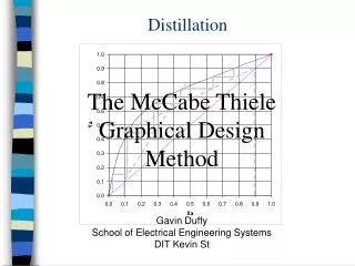
3- Shortcut Methods:a)Hengstebeck’s • It’s also called Pseudo binary system method. • System is reduced to an equivalent binary systemand is then solved by McCabe-Thiele method graphically. • The only method that solves the multi-component systems graphically (in our course of course). • Used as for preliminary design work.
Logically ... • Using the concept of light and heavy key components • So, we can consider the system as a binary system where it’s desired to separate the light key from the heavy key. According to that the molar flow rate of the non-key components can be considered constant. **** Also the total flow rates of vapour and liquid are considered constant. The method used for these calculations was developed by R.J.Hengstebeck, that’s why it’s called Hengstebeck’s method.
Hengstebeck’s Method Let’s say that: V=total molar vapour flow rate in the top section L=total molar liquidflow rate in the top section V’=total molar vapour flow rate in the bottom section L’=total molar liquidflow rate in the bottom section yni=mole fraction of component “i” in vapour phase on tray “n” xni=mole fraction of component “i” in liquid phase on tray “n” uni=molar vapour flow rate of component “i” from stage “n” lni=molar liquid flow rate of component “i” from stage “n” di=molar liquid flow rate of component “i” in top product wi=molar liquid flow rate of component “i” in bottom product a
Hengstebeck’s Method This means that: uni=yni*V u'ni=y’ni*V’ lni=xni*L l’ni=x’ni*L’ di=xDi*D wi=xWi*W yni=uni/V y'ni=u'ni/V’ xni=lni/L x’ni=l’ni/L’ a
Hengstebeck’s Method To reduce the system to an equivalent binary system we have to calculate the flow rates of the key components through the column (operating line slope is always L/V) The total flow rates (L and V) are constant, and the molar flow rates of non key components are constant, then we can calculate the molar flow rates of key components in terms of them. NOTE: The total flow rate is constant and the molar flow rates of non key components are constant, this does not mean that the molar flow rates of key components are constant as the mass transfer is equimolar. a
Hengstebeck’s Method If Le and Ve are the estimated flow rates of the combined keys. And li and ui are flow rates of the non-key components lighter than the keys in the top section. And l’i and u’i are flow rates of the non-key components heavier than the keys in the bottom section. Then slope of top section operating line will be Le/Ve And slope of bottom section operating line will be L’e/V’e SO: Le=L-SliVe=V-Sui L’e=L’-Sl’iV’e=V’-S’ui a
Hengstebeck’s Method The final shape of the x-y diagram will be as shown We need to calculate: Le (or li’s) • Ve (or ui’s) • L’e V’e Le/Ve L’e/V’e
Hengstebeck’s Method To calculate them we will need to calculate “a” where “a” is the relative volatility WITH RESPECT TO THE HEAVY KEY FOR ALL COMPONENTS. So for components heavier than the heavy key a<1 And for components lighter than the heavy key a>1
Hengstebeck’s Method For TOP SECTION Equilibrium Relation: yi=Ki.xi For heavy key: Material balance: ui=li+di And di/li=0
Hengstebeck’s Method For TOP SECTION Equilibrium Relation: yi=Ki.xi For any light non-key component: Material balance: ui=li+di
Hengstebeck’s Method For BOTTOM SECTION Equilibrium Relation: yi=Ki.xi For Light key: Material balance: l’i=u’i+wi And
Hengstebeck’s Method For BOTTOM SECTION Equilibrium Relation: yi=Ki.xi For any heavy non-key component: Material balance: l’i=u’i+wi
2) Estimate the number of ideal stages needed in the butane-pentane splitter defined by the compositions given in the table below. The column will operate at a pressure of 8.3 bar, with a reflux ratio of 2.5. The feed is at its boiling point. Compositions of feed, top and bottom products are shown in table below: Equilibrium constants were calculated and found to be:
Light key will be: n-C4 Heavy key will be: i-C5 SO aC3=5/1=5 aiC4=2.6/1=2.6 anC4=2/1=2 aiC5=1/1=1 anC5=0.85/1=0.85
For Top section: Le=L-Sli L=R*D=2.5*45=112.5 Kmoles Le=112.5-10.625=101.875 Kmoles And Ve=V-Sui V=(R+1)*D=3.5*45=157.5 Kmoles Ve=157.5-30.625=126.875 SOLe/Ve=0.8
For Bottom section: L’=L+F (feed is at its boiling point) L’=112.5+100=212.5 Kmoles V’=V=157.5 Kmoles V’e=V-Su’i Ve=157.5-25.87=131.63 Kmoles And L’e=L’-Sl’I L’e=212.5-60.87=151.63 Kmoles So L’e/V’e=1.15
Equilibrium curve: NTS in top section 6 NTS in bottom section Reboiler+5.5
3- Shortcut Methods:b) Gilliland, Fenske , Underwood Method • It is an empirical method for calculating number of stages in Multi-component distillation. • I t is composed of 3 equations to work with. 1- Gilliland equation (Has graph.): Used to calculate N stages(In this equation min. reflux ratio and min. number of stages is need) 2- Fenske equation: Used to calculate (N stages )min 3- Underwood equation: Used to calculate minimum reflux ratio
3- Shortcut Methods:b) Gilliland, Fenske , Underwood Method 1- Gilliland equation: 2- Fenske equation: 3- Underwood equation: q: (Hv-hf)/ (Hv-hL) Where θ: is a relative volatility lies between the relative volatility of light and heavy components.
3- Shortcut Methods:b) Gilliland, Fenske , Underwood Method(Gilliland Chart to use instead of equation)
3) A mixture of Hexane, Heptane, and Octane is to be separated to give the following products. Use the shortcut method to: a) Calculate the approximate minimum number of stages b) Calculate the approximate minimum reflux ratio c) Show how to get the approximate number of stages Note: The feed is liquid at its bubble point.
- Calculate from Underwood Equation as follows: Feed is saturated liquid so, (q=1) The above is one equation in one unknown; however, it will be solved using trial and error Note: the value of will lie between the relative volatilities of the light and heavy keys (Heptane and octane respectively) Get = 1.1725
- Calculate Rmin from Underwood Equation as follows: Rmin = 0.8287 - Calculate Nmin from Fenske Equation: Nmin = 14.13 • Finally to get approximate number of stage 1-ass. R=1.5Rmin=1.243 2-Get (R-R min)/(R+1)=0.185 3- Go to Gilliland chart and get the ratio (N-Nmin)/(N+1)=0.462 4- Knowing Nmin you can get N=27.13