Download
1 / 89
1.25k likes | 2.59k Vues
Distillation. CONTENTS. Flash Distillation. Differential Distillation. Distillation. Continuous Distillation with Reflux. Simple Steam Distillation. Plate Efficiencies. 1. Distillation. 9-1 Introduction.

E N D
CONTENTS Flash Distillation Differential Distillation Distillation Continuous Distillation with Reflux Simple Steam Distillation Plate Efficiencies
1 Distillation 9-1 Introduction • It is a unit operation of separation of liquid mixtures into their several components by partial vaporizing and partial condensing, and the most widely used method of achieving this end one of the major operations in chemical and petroleum industries, and the key operation of the oil refinery. The unit operation makes use of difference in volatility of individual components in a mixture. Throughout the chemical industry the demands for pure products, coupled with a relentless pursuit of greater efficiency, has necessitated continued research into the techniques of distillation.
2 Partial Vaporisation and Partial Condensation A D t1 K M N t’ L E Dew point curve t2 B t3 G C Boiling curve J y1 0 1.0 x1 x2 x3 x4 x or y benzene - toluene • Abscissa-x represents the mole fraction of the volatile component in the liquid • Ordinate-y represents the temperature at which the mixture boils; boiling curve ABCJ; dew point curve ADEJ • If a mixture of initial composition x2 is at a t3 below its boiling point t2 , as shown by point G
On the diagram, then on heating at constant pressure the following changes will occur: • a) When T reaches T2 , the liquid will boil, as shown by point B, and some vapor of composition y2, shown by point E, is formed. • b) On further heating, the composition of the liquid will change because of the loss of the more volatile component to the vapor and the boiling point will therefore rise to some t’. At this temperature the liquid will have a composition represented by L, and the vapor a composition represented by N. The mass ratio of liquid remained to the vapor formed is (lever rule)
c) On further heating to t1, all liquid is fully vapourised to give vapor D, of same composition y1 as the original liquid. • It is seen that partial vaporisation of the liquid gives a vapor richer in the more volatile composition than the liquid. If the vapor initially formed, as for instance at point E, is at once removed by conden- sation, then a liquid of x3 is obtained, represented by C. The step BEC may be regarded as representing an ideal stage, since the liquid passes from x2to x3, which represents a greater enrichment in the more volatile component than can be obtained by any other single stage of vaporisation.
Starting with superheated vapor represented by H, on cooling to D condensation will commence, and the first drop of liquid will have a composition of K. Further cooling to temperature t’ will give liquid L and vapor N. Thus partial condensation brings about enrichment of the vapor in the more volatile component in the same manner as partial va-porisation. The industrial distillation column is. in essence, a series of units in which these two processes of partial vaporisation and condensation are effected simultaneously.
3 Raoult’s and Henry’s Laws • 1. By Dalton’s law of partial pressures, the total pressure is equal to the summation of the partial pressure, that is • Then, since in an ideal gas or vapor the partial pre –ssure is proportional to the mole fraction of the constituent: • For an ideal mixture, the partial pressure is related to the concentration in the liquid phase by Raoult’s law which can be written
where is the vapor pressure of pure A at the same temperature. This relation is usually found to be true only for high values of xAor correspondingly low values of xB , but mixture of organic isomers and some hydrocarbons follow the law closely. • For low values of xA, the relation between pAand xA can be expressed by Henry’s law, that is where H is the Henry’s constant, and not the vapor pressure of the pure material.
Vapor pressure A G B F E C O 0 D Fig.9.1 Mole fraction in liquid x • If the mixture follows the Raoult’s Law, then the vapor pressure of a mixture can be obtained graphically from a knowledge of the vapor pressure of the two components. Thus, in fig. 9.1 OA represents the partial pressure of pA of A in a mixture, and CB the partial pressure of B. BA the total pressure. Thus, in a mixture of composition D, the partial pressure pA is given by DE,pB by DF, and the total P pressure by DG.
2. Boiling Equation • If it is known that the mixture follows the Raout’s Law, then the values of yA for various values of xAmay becalculated from a knowledge of the vapor pressure of the two components at various temperature. Thus • Giving
3 Relative Volatility • We have known that the distillation unit operation makes use of difference in volatility of individual components in a mixture to separate the liquid mixture into several components. How is the volatility of a component measured? 1.volatility • The volatility is defined as the ratio of the partial pressure to the mol fraction in the liquid, that is
2. Relative Volatility • In order to measure the difference in volatility, a relative volatility usually be defined as the ratio of these two volatility, that is • Substituting PyA for pA, and PyB for pB: • This gives a valuable relation between the ratio of A and B in the vapor and that in the liquid.
Since with a binary mixture, • The equation (11.6)and (11.7) can be simplified as respectively or and • This relation enables the composition of the vapor to be calculated for any desired value of x, ifis
known. For separation to be achieved, must not equal 1 and considering the more volatile component, as increases above unity, y increases and the separation becomes much easer. • From the definition of volatility and relative volati -lity of a component, it is seen that for an ideal system the volatility is numerically equal to vapor pressure of the pure component, and relative volatility to the ratio of vapor pressure of the pure components of A and B, that is
4 Methods of two-Component Mixture Distillation • Fordistillation purposes it is more convenient to plot y against x at a constant pressure, since the majority of industrial distillation take place at substantially constant pressure. This is shown as following
Mol fraction in vapor y Diagonal line Mol fraction in liquid x • This is a square with a abscissa of mol fraction x in liquid, ordinate of mol fraction y in vapor and a reference line--diagonal line. It is seen that, for a binary mixture with a normal y-x curve, the vapor is always richer in the more volatile component than the liquid from which it is formed.
There are three main methods used in distillation practice which all rely on this basic fact; they are: • 1)differential distillation. (addition) • 2)flash or equilibrium distillation • 3)rectification • Of these, rectification is much more important, and differs from the other two methods in that part of the vapor is condensed and return as liquid to the still, whereas, in the other methods, all the vapor is either removed as much, or is condensed as product.
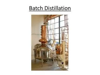
Cooling water Heating V,y y Expansion valve F,xf x pump Heating agents S,x Fig.9.3 Plant of equilibrium distillation • (Batch) differential distillation • Flash or equilibrium distillation Fig.9.2 Flow chart of batch distillation
9-2 Flash or equilibrium distillation • This method, frequently carried as a continuous process, consist of vaporizing a definite fraction of the liquid feed in such a way that the evolved vapor is in equilibrium with the residual liquid. • The feed is usually pumped through a fired heater and enters the still through a valve where the pressure is reduced. The still is essentially a separator in which the liquid and vapor produced by the reduction in pressure.
Let the concentraction of the feed be xF ; in mole fraction of the more volatile component. Let F be the molal rate of the feed, V be the molal rate of vapor withdrawn continuously, and L be the mole rate of the liquid. Let yD and xBbe the concentraction of the vapor and liquid, respectively. • By a material balance for the more volatile component gives: • Let f=V/F be the mole fraction of the feed that is vaporized and withdrawn continuously as vapor.
Combining above two Eqs. gives : (9.13) • or
9-3 Differential Distillation 1. Feature of Differential Distillation • In this process the liquid is boiledslowly and the vapors are withdrawn as rapidly as they form to a condenser, where the condensed vapor is collected. Since the vapor is richer in the more volatile component than the liquid, it follows that the liquid remaining becomes steady weaker in this component, with the result that the component of product progressively alters. Thus, whilst the vapor formed over a short period is in equilibrium with the liquid, the total vapor formed is not in equilibrium with the residual liquid.
2. Analysis of Differential Distillation • Let L be the number of mole of material in the still and x be the mol fraction of component A. After a short time, suppose an amountds, containing a mol fraction y of A, be vaporised . • The equation for material balance is (9.15)
Neglecting the term dxdL and rearranging • Integrating gives • The integral on the right side needs the information on equilibrium relation between y and x, and can be solved graphically or numerically. The average composition of total material distilled, yav, can be obtained by material balance:
9.4 Simple Steam Distillation 1. The Concepts • Where the material to be distilled has high boiling point, and particularly where decomposition might be occur if direct distillation were employed, the process of steam distillation can be used. This method is often used to separate a high-boiling component from small amounts of nonvolatile impurities. • If a layer of liquid water(A) and an immiscible high-boiling component (B) are boiled at 1atm, then, by the phase rule, for three phases and two components, F=2-3-2=1degree of freedom
When the sum of separate vapor pressures equals the total pressure, the mixture boils and • Then the vapor composition is • Note that by steam distillation, as long as liquid water is present, the high-boiling component B vaporizes at a temperature well below its normal boiling point without using a vacuum. The vapor of water (A) and high-boiling component (B) are usually condensed in a condenser and the resulting two immiscible liquid phase seperated.
The ratio moles of B distilled to moles of A distilled is: • Where the subscript A refers to the component being recovered, and B to steam, and m-mass; M-molecular weight; P-total pressure; pA,pB-partial pressure of A,and B.
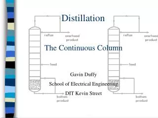
9-5 Continuous distillation with reflux • For large-scale production, continuous distillation, is often used to separate components of comparable volatility, which requires the use of distillation with reflux.
1 The Continuously Fractionating Process • The operation of a typical fractionating column may be followed by reference to Fig.9.4. The column consists of a cylindrical structure divided into sections by a series of perforated trays which permit the upward flow of vapor. The liquid reflux flows across each tray, over weir, down a downcomer to the tray below. The vapor rising from the top tray pass to a condenser and then via an accumulator or reflux drum and a reflux divider where part is withdrawn as the overhead product D, and the remainder is returned to the top tray as reflux R .
vapor condenser Warm cooling water Rectifying section Liquid reflux L xD accumulator y1 cooler Cooling water Overhead product D xD Reflux pump Stripping section Feed plate Vapor Re-boiler ys steam liquid condensate trap Bottom cooler Feed F,xf Bottom product W, xw Fig.9.4 Continuous fractionating column with rectifying and stripping sections
The liquid in the base of the column is frequently heated, either by condensing stream or by a hot oil stream, and the vapor rise through the perorations to the bottom tray. • This operation of partial condensation of the rising vapor and partial vaporisation of the reflux liquid is repeated on each tray. Vapor of composition of y1 from the top tray is condensed to give the top product D and the reflux R, both of the same the composition y1. The feed stream is introduced on some intermediate tray where the liquid has approximately the same composition as the feed. The part of the column above the feed point is known as the rectifying section; the lower portion is known as the stripping section.
In the arrangement discussed above, the feed is introduced continuously to the column and two products streams are obtained, one at the top much richer than the feed in the MVC, and the second from the base of the column weaker in the MVC. This is operation of Continuous fractionating. For the separation of small quantities of mixtures, a batch still may be used (commonly in the fine organic chemical industry), which will be discussed in more detail later.
2 Action on an ideal plate • On an ideal tray, by definition, the liquid and the vapor leaving the tray are brought into equilibrium. Consider a single tray in an ideal cascade, such as tray n in fig.9.5.
Ln-2 xn-2 Vn-1 yn-1 Tray n-1 Vn yn Ln-1 xn-1 Tray n Ln xn Vn+1 yn+1 Tray n+1 Ln+1 xn+1 Vn+2 yn+2 Fig 9.5 • Assume that the trays are numbered serially from the top down and that the tray under consideration is thenth tray from the top. Then the tray immediately above tray n is tray n-1, and that immediately below it is n+1. Subscripts are used on all quantities to show the point of origin of quantity. • Two fluid streams enter the nth tray, and two leave it.
A stream of liquid Ln-1mol/h from tray n-1 and a stream of vapor Vn+1mol/h from tray (n+1) are brought into intimate contact. A stream of vapor Vn mol/h rises to tray n-1, and a stream of liquid Ln mol/h descends to tray n+1, and the concentrations entering and leaving the nth tray are as follows: • Vapor leaving tray yn; liquid leaving tray xn; • Vapor entering tray yn-1; liquid entering tray xn-1. • By the definition of ideal tray there is equilibrium relationship between xn and yn. That is
Partial condensation Partial vaporisationg xn xn-1 yn 1.0 yn+! 0 Mol fraction of A x or y Fig.9.6 • This shown in fig.9.6.The vapor is enriched in the more volatile component A as it rises through the column. • And the liquid,is depleted of A as it flows downward. • Thus the concentration of A in both streams of vapor and liquid increase with the height of the column; that is . Although the streams leaving the tray are in equilibrium, those entering it are not. This can be seen from fig.9.6
3 Material Balances in Plat Columns D, xD F, xf W, xw 1. Overall material balances for two-component system • How many top and bottom products can be obtained for a given feeds and required quality? • The material balance for a total column gives • The material balance on the more volatile component A is
Thus: • And • The quantities of top and bottom products D, W dependthefeed rate F and the concentration of xf, and the required product qualities of xD, and xw. • The following equations apply: • Subscript m is uesd in place of n to designate a general palte in the stripping section.
2. Operating lines • The relationship of concentrations of the vapor and liquid leaving an ideal plate abides by the equilibrium curve. What rule should the relation between concentrations of the vapor leaving an ideal plate and of the liquid entering it obey? • Since a stream of feed is introduced at feed plate, the continuity of material flow in the rectifying section is different from that in the stripping section. • Thus the situations of rectifying section and stripping section must be considered separately.
V1 L D, xD n Ln,xn Vn+1, yn+1 F, xf n+1 m Lm,xm Vm+1,ym+1 m+1 W, xw Fig.9.8 1) Material balance in Rectifying section • A material balance above plate n in rectifying section Gives: • Expressing this balance on the more volatile component: • Thus:
Eliminating Vn+1 by Eq.(9.23),giving: The Eq.(9.26) is called the equation of the operating line in the rectifying section.
2) Material balance in stripping section • Similarly, taking a material balance for the total stream and for the more volatile component from the top to above mth plate and • Thus:
In a different form of Eq.(9.27a): • The equation gives the relation between the compositions of the vapor rising to a plate and the liquid on the plate in the stripping section. It is called the equation of operating line for the stripping section of a column.
4 Number of plates 1 .constant molar overflow • If the molar heats of vaporisation are approximately constant, the flows of liquid and vapor in each part of the column will not vary from tray to tray unless material enters or is withdrawn from the section • This is the concept of constant molar overflow.
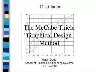
2. The method of McCabe and Thiele • The simplifying assumptions of constant molar heat of vaporisation, of no heat losses, and of no heat of mixing, led to constant molar vapor flow and constant molar liquid flow in any section of the column. We have obtained the equations of the operating lines: • Rectifying section • Stripping section
They are all straight lines. The operating line for rectifying section is a straight line of a slope , and of a intercept . If xn=xD in equation (9.26), then • and it must pass through a definite point A(xD,xD) on the equilibrium diagram x-y . Further, if xn+1=0, then yn+1= , this represents the another definite point B(0, ). The two definite points make the the operating line easily drawn out AB, as shown in fig.9.9
xD A G Mol fraction in vapor y y (xF, xF) B C x xD xF Mol fraction in liquid x Fig. 9.9 determination of number o plate
Similarly, the equation of operating line for stripping section is also a straight line of slop , and if xm=xB , then • and this represents the straight line has to pass th -rough the point C(xB,, xB). The operating line for stripping section is easy to be drawn out CG with use of the slop and the point C(xB,, xB) as shownin fig.9.10.
When the two operating lines have been drawn out, the number of theoretical plates required can be determined by drawing steps between the equ -ilibrium curve and the operating line starting from point A. The method is called McCabe-Thiele’s.