Download
1 / 14
140 likes | 290 Vues
EUSO Calibration Concept. Absolute Ground Calibration of entire instrument completed prior to launch In-flight calibration/monitored with LED array mounted on inside cover of shutter FOV measured by raster scans with LIDAR

E N D
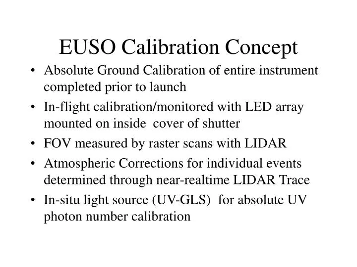
EUSO Calibration Concept • Absolute Ground Calibration of entire instrument completed prior to launch • In-flight calibration/monitored with LED array mounted on inside cover of shutter • FOV measured by raster scans with LIDAR • Atmospheric Corrections for individual events determined through near-realtime LIDAR Trace • In-situ light source (UV-GLS) for absolute UV photon number calibration
UV Ground Light Source • Provide calibration data to confirm signal losses in the atmosphere • 3 versions: • Air-borne Module: mounted on dedicated airplane flights for EUSO • Serviced Module: Units located at specific places that can provide power and communication links (i.e. observatories etc…) • Stand-alone Module: Distributed at key locations where access/power/telemetry may not be available
UV-GLS flux estimate Energy output density per flash: 0.003 J/cm2-nm @ distance of 0.5m Useful band width (300-400nm): 100 nm Useful Energy output per flash: 0.3 J/cm2 @ distance of 0.5 m Reduction in signal by distance: (0.5m/400,000m)2 = 1.610-12 Energy per flash reaching EUSO: 4.710-19 J/cm2 @ distance of 400 km Photons per flash at EUSO: 4.7x10⁻¹⁹/5.710-19 = 0.8 /cm2 EUSO collector 2m dia. 3.14104 cm2 Photons in EUSO FOV per flash: 0.831.4103 = 2.610 4’s Transmission loss through lens/filter 50% Transmission loss through atmosphere 50% PMT quantum efficiency 20% Total losses: 95% Photo electrons: 2.6104 0.05 = 1300 p.e.s./per flash
UV-GLS Development Costs Unmanned Serviced Air-borne 1) CPU $400 $400 $400 2) ADC $250 $250 $500 3) Enclosure $150 $150 $500 4) Flash lamp $500 $1500(3) $1950(3) 5) Trigger circuit $180 $540(3) $750(3) 6) HV-supply $575 $1725(3) $2250(3) 7) Cooling Shield $245 $735(3) $1020(3) 8) Capacitor $230 $690(3) $870(3) 9) Diffuser $250 $750(3) $750(3) 10) Filter $10 $350(3) $350(3) 11) Photo-diode $100 $100 $100 12) Power supply $250 $250 $250 13) Light Sensor $25 $25 14) Solar array $250 $250 15) Battery $50 $50 Sub-Total $3480($2500) $7465($4000) $9690 Other Development Costs: CCD system $7500 Test setup $10,000 Stage $5000 Technician (1yr) $50,000 Sub-Total $72,500
Air-Borne ModuleDeployment Plane: P3BTwin Otter Platform: 16” diameter turret on top of fuselage must make adapter Altitude: 20-25 kft ( 6-7.5 km) 20 kft maximum Duration: 8-10 hrs Speed: 300 knots Range: 300 miles Initial costs: $15,000 $15,000 Flight rate: $3000/hr ($7000/hr full cost) $1100/hr ($1700 full) Travel: for airfields other than Wallops, contractor travel and overtime
Candidate Ground Base Locations 1) Mauna Kea, Hi 20oN 4.1 km 2) Mt. Fowlkes, Tx 31oN 2.1 km 3) Mt. Hopkins, Az 32oN 2.6 km 4) Mt. Palormar, Ca 33oN 1.9 km 5) Nizhny Arkhyz, Russia 43oN 2.1 km 6) Coonabararan, Australia 31oS ? km 7) Cerro La Salle Chile 29oS 2.4 km 8) La Palma, Canary Is. 29oN 2.4 km 9) Calar Alto, Spain 37oN 2.2 km 10) Jelm Mtn., Wyoming 41oN 2.9 km 11) Hemle, India ~30oN 4.2 km Sea Level: your favorite dark vacation spot