Download
1 / 61
610 likes | 803 Vues
An Overview of JPEG-2000. Michael WMarcellin, Michael J Gormish + , Ali Bilgin, Martin PBoliek + University of Arizona, + Ricoh Silicon Valley DCC 2000. Abstract. A brief history of the JPEG-2000 standardization process An overview of the standard

E N D
An Overview of JPEG-2000 Michael WMarcellin, Michael J Gormish + , Ali Bilgin, Martin PBoliek + University of Arizona, + Ricoh Silicon Valley DCC 2000
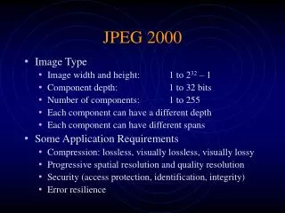
Abstract • A brief history of the JPEG-2000 standardization process • An overview of the standard • Some description of the capabilities provided by the standard • Part I of the JPEG-2000 standard specifies the mini mum compliant decoder • Part II describes optional, value-added extensions
1 Introduction • Motivated by Ricoh’s submission of the CREW (Compression with Reversible Embedded Wavelets) algorithm (for JPEG-LS) • JPEG-LS — a lossless and near-lossless compression
1 Introduction • List of features: • State-of-the-art low bit-rate compression performance • Progressive transmission by quality resolution, component, or spatial locality • Lossy and lossless compression • Random (spatial) access to the bitstream • Pan and zoom • Compressed domain processing (eg, Rotation and cropping) • Region of interest coding by progression • Limited memory implementations
2 The JPEG-2000 Development Process 031997 WG1 meeting in Sydney released a CDROM containing 40 test images 00625 to 20 bits per pixel (bpp), and lossless Wavelet/Trellis Coded Quantization (WTCQ) (submitted by SAIC/UA) 031998 WG1 meeting in Geneva create a JPEG-2000 “Verification Model” (VM)
2 The JPEG-2000 Development Process The WTCQ Algorithm Basic ingredients: The discrete wavelet transform, TCQ(Trellis Coded Quantization, Using step sizes chosen via a Lagrangian rate allocation procedure), and binary arithmetic bitplane coding VM0 - VM2 VM3 - VM5
2 The JPEG-2000 Development Process VM0-VM2 Supported user specified floating point and integer transforms, as well as user specified decompositions(dyadic, uniform, etc) A fixed quantization table(“Q-table”) alternative to the Langrangian rate allocation scalar quantization was included in VM2 tiling, region of interest coding/decoding, error resilience, approximate wavelet transforms with limited spatial support
2 The JPEG-2000 Development Process VM0-VM2 De-interleaving of bitplanes Significant, Refinement, Insignificant for steepest rate-distortion slopes appear first in an embedded bitstream no inter-subband dependencies (Parallelism) change the type of progression without decoding Improvements to the context modeling
2 The JPEG-2000 Development Process VM3 - VM5 Nov 1998 WG1 meeting in Los Angeles EBCOT (embedded block coding with optimized truncation) dividing each subband into rectangular blocks of coefficients and performing the bitplane coding independently on these “code-blocks” reduces memory requirements included an efficient syntax for forming the sub-bitplane data of multiple code-blocks into “packets,” which taken together form quality “layers”
2 The JPEG-2000 Development Process VM3 - VM5 Mar 1999 WG1 meeting in Korea MQ-coder (submitted by Mitsubishi) adopted as the arithmetic coder for JPEG-2000 QM-coder used in the JBIG-2
3 Final Standardization • Schedule: • Dec 1999 “Committee Draft” (CD) • Apr 2000 “Final Committee Draft” (FCD) • Aug 2000 “Final Draft International Standard” (FDIS) • Dec 2000 “International Standard” (IS) • Jul 2001 PART II
3 Final Standardization • PART I “minimum decoder” • PART II “extensions” , “value added” • PART III “Motion JPEG-2000” • PART IV JPEG-2000 compliance tests • PART V development of free software • JJ2000 group (Cannon France, Ericsson, EPFL) => JAVA • UBC => C
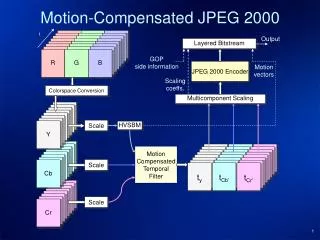
4 JPEG-2000 Coding Engine Tiles and Component Transforms Partitions, Transforms, and Quantization Block Coding Packets and Layers
41 Tiles and Component Transforms Divide the image into rectangular, non-overlapping tiles on a regular grid Arbitrary tile sizes are allowed Each tile of a component must be of the same size YCbCr, Reversible Component Transform (RCT) (allow lossless reconstruction of all components)
42 Partitions, Transforms, and Quantization Transforms Given a tile, L-level dyadic(pyramidal) wavelet transform is performed using either the floating point wavelet , or the integer wavelet(for lossless) For more memory efficient implementations are possible using sliding window or block-based transform techniques
42 Partitions, Transforms, and Quantization Transforms (L-level transform) “L+1” different size or resolutions lowest frequency subband(LFS) as resolution 0, also referred to as the resolution level 0 subband j -> j+1 is referred to collectively as resolution-level j+1 subbands
42 Partitions, Transforms, and Quantization Quantization One quantization step size is allowed per subband Step sizes can be chosen in a way to achieve a given level of “quality” The standard places no requirement on the method used to select quantization step sizes Integer wavelet => Q=1.0, rate control through truncation of embedded bitstreams Packet partition
42 Partitions, Transforms, and Quantization Packet partition Provided a medium-grain level of spatial locality in the bitstream, streaming, and (spatial) randomaccess to the bitstream Code-blocks are obtained by dividing each packet partition location into regular non-overlapping rectangles
an image is divided into tiles and each tile is transformed The subbands are divided into packet partition locations Each packet partition location is divided into code-blocks Recap
Bitplanes Three pass Significance Refinement Clean-up All coding is done using context dependent binary arithmetic coding Block Coding 1st MSB 2ed MSB Least MSB
Block Coding • For brevity, JPEG-2000 uses no more than nine contexts to code any given type of bit (ie, significance, refinement, etc)
Packets and Layers • A Packet can be interpreted as one quality increment for one resolution level at one spatial location • A Layer can be interpreted as one quality increment for the entire • image at full resolution • current VM supports approximately 50 layers
5 JPEG-2000 Bitstream Provides better rate-distortion performance, for any given rate, then the original JPEG Progression can be changed, additional quantization can be done, or a server can respond only with the data desired by a client, all without decoding the bitstream
5 JPEG-2000 Bitstream Progression resolution, quality, spatial location, and component Achieved by the ordering of packets within the bitstream Progression type can be changed at various places within the bitstream Allows an icon to be displayed first, then a screen resolution image
5 JPEG-2000 Bitstream Parsing a parser can read all the markers, change the type of progression in the markers, write the lengths of the packets out in the new order, and write the packets themselves out in the new order When sending a color image to a grayscale printer, there is no point in sending color information Fifty layers are provided
5 JPEG-2000 Bitstream Spatial Accessibility “Parsing” from one file to another file Regions of interest (ROI) All of the code-blocks which contain coefficients affecting the ROI can be identified, and the bitplanes of those coefficients can be stored in higher layers relative to other coefficients
5 JPEG-2000 Bitstream Image Editing and Compression Allow uncompressed tiled image formats allow regions of and image to be edited, and only those tiles affected need to be rewritten to disk PART I allow 90,180, and 270 degree rotations, and horizontal and vertical flips of an image PART II flagged in the bitstream, and left for the decoder to perform
6 Performance 2048 by 2560
7 Conclusion • ISO sells copies of the specification but only after the “International Standard” stage is reached • JPEG-2000 is unlikely to replace JPEG in low complexity applications at bitrates in the range where JPEG performs well • For applications requiring either higher quality or lower bitrates, or any of the features provided, JPEG-2000 should be a welcome standard
Data ordering • Annex B Data ordering • B.1 Image division into components • B.2 Image division into tiles and tile-components • B.4 Tile-component division into resolutions and sub-bands • B.5 Division of resolutions into precincts • B.6 Division of the sub-bands into code-blocks • B.7 Layers • B.8 Packets • B.9 Packet header information coding • B.10 Tile Data and Tile-Parts • B.11 Progression Order.
B7, B8, B9, B10 • B7 Layers • B8 Packets • B9 Packet header information coding • B10 Tile Data and Tile-Parts
Annex C Arithmetic entropy coding • C.1 Binary encoding (informative) • C.2 Description of the arithmetic encoder (informative) • C.3 Arithmetic decoding procedure
Annex D Coefficient bit modeling • D.1 Code-block scan pattern within code-blocks • D.2 Coefficient bits and significance • D.3 Decoding passes over the bit-planes • D.4 Initializing and terminating • D.5 Error resilience segmentation symbol • D.6 Selective arithmetic decoding bypass • D.7 Vertically causal context formation • D.8 Flow diagram of the code-block coding
Annex D Coefficient bit modeling • D.1 Code-block scan pattern within code-blocks
Annex D Coefficient bit modeling • D.3 Decoding passes over the bit-planes • Significance propagation decoding pass • Magnitude refinement pass • Cleanup pass
Annex E Quantization • E.1 Scalar coefficient dequantization (normative) • E.2 Scalar coefficient quantization (informative)
Annex F Discrete wavelet transformation of tile components • F.1 Introduction and overview • F.2 The inverse discrete wavelet transformation (normative) • F.3 Forward Transformation (informative)
Annex G DC level shifting and component transformations • G.1 DC level shifting of tile components • G.2 Reversible component transformation (RCT) • G.3 Irreversible component transformation (ICT • G.4 Chrominance component sub-sampling and the image reference grid (informative)