Download
1 / 62
690 likes | 883 Vues
JPEG 2000: An Introduction. Agenda. Overview Wavelet transform EBCOT - JPEG2000 coefficient modeling and context encoding MQ arithmetic coding ROI: Region of Interests. Overview. Introduction.

E N D
Agenda • Overview • Wavelet transform • EBCOT - JPEG2000 coefficient modeling and context encoding • MQ arithmetic coding • ROI: Region of Interests
Introduction • Joint Photographic Experts Group (JPEG) is an ISO standard committee with a mission on “Coding and compression of still images”. • JPEG coding standard (1988): DCT (discrete cosine transform) based transform coding to compress bit-map images. • JPEG2000 efforts started in 1996 to use new methods such as fractals or wavelets. The target deliver date is year 2000 and hence the name.
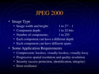
JPEG2000 Features • High compression efficiency • Lossless color transformations • Lossy and lossless coding in one algorithm • Embedded lossy to lossless coding • Progressive by resolution and quality • Static and dynamic Region-of-Interest • Error resilience • Visual (fixed and progressive) coding • Multiple component images • Palletized Images
Handling Large Images • Partition in both spatial and frequency domain • Spatial Domain Partition: Tile, Frame • bit streams of different tiles or frames are not independent • artifact may occur at boundaries • Special wavelet transform: • Spatially segmented wavelet transform (SSWT) • Line based wavelet transform • Block: Independent partition in frequency domain (wavelet coefficients) • bit streams are independently generated
JPEG at 0.125 bpp (enlarged) C. Christopoulos, A. Skodras, T. Ebrahimi, JPEG2000 (online tutorial)
JPEG2000 at 0.125 bpp C. Christopoulos, A. Skodras, T. Ebrahimi, JPEG2000 (online tutorial)
Wavelet Based Image Coding Discrete Wavelet Transform Entropy coding Context-based Quantization 2D discrete wavelet transform converts images into “sub-bands” Upper left is the DC coefficient Lower right are higher frequency sub-bands.
y2 y0 y1 y3 p /8 p /4 p /2 p 1D Discrete Wavelet Transform HO: low pass digital filter, H1: high pass digital filter. Z-1: delay, 2: down-sample by 2 Recursive application of wavelet transform in spatial domain corresponds to dyadic partition of data in the frequency domain.
2D Separate DWT • 1D DWT applied alternatively to vertical and horizontal direction line by line. • The LL band is recursively decomposed, first vertically, and then horizontally. • This is Mallat method. Other methods have also been proposed. L H LL LH Image in spatial domain HL HH LH LH HL HH HL HH
Bit Plane Coding • Coefficients are represented in sign-magnitude format • Bit plane starts from the most significant bit (MSB) • Sign bit is encoded after the MSB is encoded. • Context (surrounding bit patterns) at each bit plane is examined. • Key: explore patterns in binary bit-plane. MSB LSB
Set Partitioning in Hierarchical Trees. Amir Said and William Pearlman (IEEE Trans. CSVT, 1996) Based on zero tree wavelet coding Main ideas: Partial magnitude sorting of wavelet transformation coefficients Ordered bit plane transmission Exploitation of the self-similarity among wavelet coefficients between sub-bands having parent-descendent relations. SPIHT
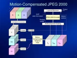
JPEG2000 • Image components, tiles, and sub-band structures • Wavelet transform • Coefficient modeling • Arithmetic coding
Tiling XTOsiz + XTsiz > XOsiz, YTOsiz + YTsiz > YOsiz
Image 3HL 4LL 2HL 3LH 3HH Image components 1HL 2LH 2HH Tiles resolution Sub-band precinct Code block 1LH 1HH layers packet Image Structure
Layered Bit stream • Each bit stream is organized as a succession of layers • Each layer contains additional contributions from each block (some contributions might be empty) • Block truncation points associated with each layer are optimal in the rate distortion sense • Rate distortion optimization can be performed but it does not need to be standardized
Purpose of component transform is to de-correlate among components. For multi-spectral images, PCA may be used. There are reversible and irreversible transforms. DC level shift and component transform Forward reversible component transform Inverse reversible component transform
Make lossless color coding possible. All components must have identical sub-sampling parameters and same depth Reversible Color Transform
IDWT Procedure IDWT levNL Done yes I(x,y) aoLL(x,y) lev0 no a(lev1)LL(u,v) = 2D_SR(alevLL(u,v), alevHL(u,v), alevLH(u,v), alevHH(u,v)) Iev lev1
Reversible Integer DWT DWT coefficients are integers without any truncation error provided image component pixel values are also integer-valued. Transform is exactly reversible. Non-causal filter. Lossless 1D DWT Reverse transform Forward transform I01 2n+1 < i1 1; I0 2n < i1 ; I01 2n < i1 1; I0 2n+1 < i1 ; Xext(), Yext(): symmetrically, cyclic extended signals.
Daubechies’ (9,7) filter in the lifting format. Step 1: i03 2n < i1+3 Step 2: i02 2n+1 < i1+2 Step 3: i03 2n < i1+3 Step 4: i02 2n+1 < i1+2 Step 5: i01 2n < i1+1 Step 6: i0 2n+1 < i1 Lossy 1D DWT Step 1: i03 2n+1 < i1+3 Step 2: i02 2n < i1+2 Step 3: i01 2n+1 < i1+1 Step 4: i0 2n < i1 Step 5: i0 2n+1 < i1 Step 6: i0 2n < i1 • = 1.586 134 342, = 0.052 980 118 = 0.882 911 075, = 0.443 506 852 • K = 1.230 174 105
Row-based Wavelet Transform • Problem with traditional wavelet transform: • filtering to be performed in both vertical and horizontal directions. While access in one direction is easy, access in the other will require whole image to be buffered • Difficult for implementation on PDA or other hand-held devices with limited amount of main memory. • Row-based wavelet transform • consumes the minimum amount of resources, • gives same results as traditional wavelet transform • Method • Use a rolling window for each decomposition level to keep enough number (five) rows of image data in on-chip memory.
Context Coding Algorithm: EBCOT • Embedded Block Coding with Optimal Truncation • Block Coding • Divide each sub-band into code blocks of samples which are coded independently • For each block, a separate bit-stream is generated without utilizing any information from any of the other blocks • Optimal Truncation • The bit-stream of each block can be truncated to a variety of discrete lengths, with associated distortion • A post-processing step after all blocks are compressed determines truncation point for each block
EBCOT Block Coding • Taubman and Zakhor (IEEE Trans. IP, Sep. 94). • Layered Zero Coding with Fractional Bit-Planes. • For each bit plane, the encoding is applied three passes. • Four types of coding operations for Arithmetic Entropy Coding: • Zero Coding (ZC) • Run-Length Coding (RLC) • Sign Coding (SC) • Magnitude Refinement • Usage rule: If a pixel is not yet significant, use ZC and RLC to encode whether it is significant in the current bit plane. If so, use SC to encode its sign. If a pixel is already significant, use Magnitude refinement to encode the new bit position.
Two Tiered Coding in EBCOT All the complexity is concentrated in the low-level block coding engine, T1, which generates embedded block bit-streams. The second tier, T2, plays a vital role in efficiently representing the individually coded blocks in a full-featured bit-stream. ISO/IEC JTC 1/SC 29/WG 1 N1422
Illustration of Layered Coding • Illustration of block contributions to bit-stream layers. Only five layers are shown with seven code blocks, for simplicity. • Notice that not all code blocks need contribute to every layer and that the number of bytes contributed by blocks to any given layer is generally highly variable. • Notice also that the block coding operation proceeds vertically through each code block independently, whereas the layered bit-stream organization is horizontal, distributing the embedded bit-streams for each block throughout the bit-stream.
Embedded Block Bit Stream • Pip,k: k-th pass of i-th block, p-th bit plane (1 p Mi1) • Scanning order: for i = 1, 2, … for p = 1, 2, … Mi1 for k = 1, 2, 3 • Three passes process: • Significant Propagation Pass (Pip,1) • Magnitude Refinement Pass (Pip,2) • Clean up Pass (Pip,3)
Coefficient Bit Modeling • Wavelet coefficients are associated with different sub-bands arising from the 2D separable transform applied • These coefficients are then arranged into rectangular blocks within each sub-band, called code-blocks. • These code-blocks are then coded a bit-plane at a time starting from the most significant bit-plane with a non-zero element to the least significant bit-plane. • For each bit-plane in a code-block, a special code-block scan pattern is used for each of three coding passes. • Each coefficient bit in the bit-plane is coded in only one of the three coding passes: • significance propagation, • magnitude refinement, and • cleanup.
Three Passes Scanning • Significant Pass • Scanning all insignificant samples which have at least one significant neighbors to determine if it will become significant at current bit plane. • Use ZC to encode if a sample is still insignificant. • If a sample becomes significant, also apply SC to encode its sign bit. • Magnitude Refinement Pass • Scanning samples which became significant in a previous bit-plane using MR encoding. • Normalization Pass • Scanning all remaining samples and encode using ZC + RLC
Each bit plane with a code block is scanned during the context coding process in a specific order. All quantized transform coefficients are represented in sign-magnitude representation. For a particular sub-band, there is a maximum number of magnitude bits, Mb. The “significance state” changes from insignificant to significant at the bit plane where the most significant 1 bit is found. For a code-block, the number of bit-planes starting from the most significant bit-plane that are all zero, is signaled in the packet header Scanning Order within a code block
Each coefficient in a code-block has an associated binary state variable called its significance state. Significance states are initialized to 0 (coefficient is insignificant) and may become 1 (coefficient is significant) during the course of the coding of the code-block. Four different context formation rules are defined, one for each of the four coding operations: significance propagation pass: significance coding, sign coding, magnitude refinement pass magnitude refinement coding, cleanup pass Cleanup coding. The current context obtained during context coding is provided to the arithmetic MQ coder. Neighboring states used to form context
Bit plane encoding orders • The number of bit-planes starting from the most significant bit that have no significant coefficients (only insignificant bits) is signaled in the packet headers. • The first bit-plane with a non-zero element has a cleanup pass only. The remaining bit-planes are coded in three coding passes. • Each coefficient bit is coded in exactly one of the three coding passes. Which pass a coefficient bit is coded in depends on the conditions for that pass. • In general, the significance propagation pass includes the coefficients that are predicted, or “most likely,” to become significant and their sign bits, as appropriate. • The magnitude refinement pass includes bits from already significant coefficients. • The cleanup pass includes all the remaining coefficients.
Significance propagation pass • The significance propagation pass includes only bits of coefficients that were insignificant (the significance bit has yet to be encountered) and have a non-zero context. All other coefficients are skipped. • The context is delivered to the arithmetic decoder (along with the bit stream) and the decoded coefficient bit is returned. • If the value of this bit is 1 then the significance state is set to 1 and the immediate next bit to be decoded is the sign bit for the coefficient. Otherwise, the significance state remains 0. • When the contexts of successive coefficients and coding passes are considered, the most current significance state for this coefficient is used.
Two phases: Summarize contributions of vertical and horizontal neighbors Reduces these contributions into 1 or 5 context labels The context labels are sent to MQ arithmetic coder. Signbit = AC(contextlabel) XORbit Signbit: sign bit of the current coefficient AC(contextlabel) is the valuate returned from arithmetic decoder given the context label and the bit stream. Sign Bit Coding
Magnitude Refinement • The magnitude refinement pass includes the bits from coefficients that are already significant (except those that have just become significant in the immediately proceeding significance propagation pass). • The context used is determined by the summation of the significance state of the horizontal, vertical, and diagonal neighbors. These are the states as currently known to the decoder, not the states used before the significance decoding pass. • Further, it is dependent on whether this is the first refinement bit (the bit immediately after the significance and sign bits) or not.
Cleanup Pass • The first pass and only coding pass for the first significant bit-plane. • The third and the last pass of all the remaining bit-planes. • Use both neighbor context as in significant propagation pass and run-length coding.
Context-based Arithmetic Entropy Coding • The MQ-coder, a low complexity entropy coder is used. • Contexts are based on the significance of horizontal, vertical, diagonal neighbors of the pixel concerned. • Current there are 46 contexts.
Tagged Tree Each node has an associated current value, which is initialized to zero (the minimum). A 0 bit in the tag tree means that the minimum (or the value in the case of the highest level) is larger than the current value and a 1 bit means that the minimum (or the value in the case of the highest level) is equal to the current value. For each contiguous 0 bit in the tag tree the current value is incremented by one. Nodes at higher levels cannot be coded until lower level node values are fixed (i.e a 1 bit is coded). The top node on level 0 (the lowest level) is queried first. The next corresponding node on level 1 is then queried, and so on.
K = 0 (top level) t0(0,0) = 0 (initialize) t0(0,0) = 0 < q0(0,0) = 1 output 0, t0(0,0)= t0(0,0)+1=1 t0(0,0) = 1 = q0(0,0) = 1 output 1, K = K+1 = 1 Note: q0(0,0) is encoded! K = 1 t1(0,0) = q0(0,0) = 1 (initialize) t1(0,0) = 1 = q1(0,0) output 1, K = K+1 = 2 Note: q1(0,0) is encoded! K = 2 t2(0,0) = q1(0,0) = 1 (initialize) t2(0,0) = 1 = q2(0,0) = 1 output 1, K = K+1 = 3 Note: q2(0,0) is encoded. K = 3 t3(0,0) = q2(0,0) = 1 (initialize) t3(0,0) = q3(0,0) = 1 output 1, done Note: q3(0,0) is encoded Thus, code for q3(0,0): 01111 Tagged tree encoding example q0(0,0)=1 01 q1(0,0)=1 1 q2(0,0)=1 1 q3(0,0)=1 1
Next, encode q3(1,0). Since its parent node q2(0,0) is known, we start with K = 3: K = 3 t3(1,0) = q2(0,0) = 1 (initialize) t3(1,0) = 1 < q3(1,0) = 3 output 0, t3(1,0) = t3(1,0) + 1 = 2 t3(1,0) = 2 < q3(1,0) = 3 output 0, t3(1,0) = t3(1,0) + 1 = 3 t3(1,0) = 3 = q3(1,0), done output 1, Note q3(1,0) is encoded as 001 Now, consider q3(2,0). Its parent is q2(1,0) which needs to be encoded first. K = 2 t2(1,0) = q1(0,0) = 1 t2(1,0) = 1 = q2(1,0) output 1, K = K + 1 = 3 K = 3 t3(2,0) = q2(1,0) = 1 t3(2,0) = 1 < q3(2,0) = 2 output 0, t3(2,0) = t3(2,0)+1 = 2 t3(2,0) = 2 = q3(2,0), done output 1 Hence q3(2,0) is encoded as 101 Example continued q0(0,0)=1 01 q1(0,0)=1 1 q2(0,0)=1 q2(1,0)=1 1 1 q3(0,0)=1 q3(1,0)=3 q3(2,0)=2 1 001 01
Bit-stream is a succession of layers. Layer contains the contributions from each code block. The block truncation associated with each layer are optimal in rate-distortion sense. Single layer can achieve “progressive in resolution” Multiple layers can achieve “progressive in SNR” Layers
Basic Arithmetic Coding • MPS: more probable symbol with probability Pe • LPS: less probable symbol with probability Qe • If M is encoded, current interval is the Pe part, else, it is the Qe part (bottom). The length is kept in variable A. • Code string C points to the base of the current interval. M M L M 1.0 Pe Qe 0.0
A(0) Qe Qe Qe C(the pointer of code string) Qe 0 M M M L Context: Encoding of the Sequence MMLM • if MPS is encoded • C C+Qe • A AQe • else(LPS is encoded) • A Qe • end • if A < 0.75 • Renormalize A and C; • Update Qe; • Interval A is kept between 0.75 and 1.5. Binary 0x8000 is used to represent 0.75 to make comparison easy. • Each time A is doubled, so does C. The higher order byte of C register is overflowed to an external buffer (compressed code stream). A(the current interval)