Download
1 / 54
2.31k likes | 7.91k Vues
Right Heart Catheterization – basic right heart pressure tracings. University of Kansas August 20, 2004 Cardiac catheterization conference. The Heart. Year 1 Cardiology Fellowship. Right heart catheterization and the Swan Ganz catheter.

E N D
Right Heart Catheterization – basic right heart pressure tracings University of Kansas August 20, 2004 Cardiac catheterization conference
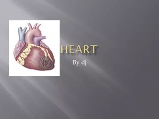
The Heart Year 1 Cardiology Fellowship
Right heart catheterization and the Swan Ganz catheter • The first to demonstrate that a catheter could be advanced safely into the human heart was the German surgeon Werner Forssmann (1904-1979) – who did the experiment on himself. A catheter similar to the Swan-Ganz was originally developed in 1953 and used in dogs by the U.S. physiologists Michael Lategola and Hermann Rahn (1912-1990). Swan and Ganz introduced their catheter into clinical practice in 1970.Bibliography: • W. Forssmann: Die Sondierung des Rechten Herzens.Klinische Wochenschrift, Berlin, 1929, 8: 2085.Experiments on myself. Translated by H. Davies. London, St. James Press, 1974.
Right Heart Catheterization • Indications • Diagnosis of shock states • Differentiation of high- versus low-pressure pulmonary edema • Diagnosis of primary pulmonary hypertension (PPH) • Diagnosis of valvular disease, intracardiac shunts, cardiac tamponade, and pulmonary embolus (PE) • Monitoring and management of complicated AMI • Assessing hemodynamic response to therapies • Management of multiorgan system failure and/or severe burns • Management of hemodynamic instability after cardiac surgery • Assessment of response to treatment in patients with PPH • Contraindications • Tricuspid or pulmonary valve mechanical prosthesis • Right heart mass (thrombus and/or tumor) • Tricuspid or pulmonary valve endocarditis
Complications • Access • Pneumonthorax • Hemothorax • Tracheal perforation • Intracardiac • Stimulation of the RVOT – ventricular arrhythmias • AV block- be aware in patients with a LBBB (consider a temporary pacemaker prior to proceding) • Causing a RBBB • Atrial arrhythmias • Pulmonary rupture • Pulmonary infarct • RV puncture
Basics - Insertion • The SGC is inserted percutaneously into a major vein (jugular, subclavian, femoral) via an introducer sheath. The predominance of right heart catheterization is performed in the invasive lab utilizing the femoral approach. Preference considerations for cannulation of the great veins are as follows: • Right internal jugular vein (RIJ) - Shortest and straightest path to the heart • Left subclavian - Does not require the SGC to pass and course at an acute angle to enter the SVC (compared to the right subclavian or left internal jugular [LIJ]) • Femoral veins - These access points are distant sites, from which passing a SGC into the heart can be difficult, especially if the right-sided cardiac chambers are enlarged. Often, fluoroscopic assistance is necessary, but these sites are compressible and may be preferable if the risk of hemorrhage is high.
Sheath Insertion • A. Puncture vessel by needle • B. Flexible guidewire placed into vessel via needle • C. Needle removed and guidewire left in place, hole in skin is enlarged with a scalpel • D. Sheath and dilator placed over the guidewire • E. Sheath and dilator advanced into the vesssel • F. Dilator and sheath removed while sheath remains in the vessel Modified Seldinger’s technique
Advancing Your Right Heart Catheter • Advance the SGC to about 20cm and inflate the balloon tip. • Initial chamber entered will be the right atrium and the initial pressure waveform will have 3 positive deflections, the a, c and v waves • There will be an x and y descent
a wave – results from atrial systole c wave – occurs with the closure of the tricuspid valve and the initiation of atrial filling v wave – occurs with blood filling the atrium while the tricuspid valve is closed Right Atrial Pressure Tracing
Timing of the positive deflections • a wave – occurs after the p wave during the PR interval • c wave – when present occurs at the end of the QRS complex (RST junction) • v wave – occurs after the T wave
Right Atrial Chamber • Height of the v wave is related to the atrial compliance and the volume of blood returning from the periphery • Height of the a wave is related to the pressure needed to eject forward blood flow • The v wave is usually smaller than the a wave in the right atrium
Elevated a wave Tricuspid stenosis Decreased RV compliance e.g. pulm htn, pulmonic stenosis Cannon a wave AV asynchrony – atrium contracts against a closed tricuspid valve e.g. AVB, Vtach Absent a wave Atrial fibrillation or standstill Atrial flutter Elevated v wave Tricuspid regurgitation RV failure Reduced atrial compliance e.g. restrictive myopathy Right atrial hemodynamic pathology
Right atrial hemodynamic pathology Note the Cannon a wave that is occurring during AV dysynchrony – atrial contraction is occurring against a closed tricuspid valve. Note the large V wave that occurs with Tricuspid regurgitation
Hemodynamic Pathology • Tricuspid Stenosis • Large jugular venous a waves on noted on exam • Notable elevated a wave with the presence of a diastolic gradient - >5mmHg gradient is considered signficant
Advancing Your Right Heart Catheter • Continue advancing the catheter into the right ventricle • The right and left ventricular pressure tracings are similar. • The right ventricular has a shorter duration of systole • Diastolic pressure in the right ventricle is characterized by an early rapid filling phase, then slow filling phase followed by the atrial kick or a wave a
Normal RV waveform artifact • Note the notch on the top of RV pressure waveform • This represents “ringing” of a fluid-filled catheter • Ringing can also be noted on the diastolic portion of the waveform
Advancing Your Right Heart Catheter • Advancing out the RVOT to the pulmonary artery • There is a systolic wave indicating ventricular contraction followed by closure of the pulmonic valve and then a gradual decline in pressure until the next systolic phase. • Closure of the pulmonic valve is indicated by the dicrotic notch
Timing of the PA pressure • Peak systole correlates with the T wave • End diastole correlates with the QRS complex
Hemodynamic Pathology • Pulmonic Stenosis • Notable large gradient across the pulmonic valve during PA to RV pullback. • Notable extreme increases in RV systolic pressures and a damped PA pressure
Elevated systolic pressure Primary pulmonary hypertension Mitral stenosis or regurgitation Restrictive myopathies Significant L to R shunt Pulmonary disease Reduced systolic pressure Pulmonary artery stenosis Ebstein’s anomaly Tricuspid stenosis Tricuspid atresia Reduced pulse pressure Right heart ischemia Pulmonary embolus Tamponade Bifid pulmonary artery waveform Large left atrial v wave transmitted backward Pulmonary artery diastolic pressure > pulmonary capillary wedge pressure Pulmonary disease Pulmonary embolus Tachycardia Pulmonary artery hemodynamic pathology
Advancing Your Right Heart Catheter • With the balloon inflated advance the catheter until the pressure tip wedges into the distal pulmonary artery (pulmonary capillary wedge pressure) • Similar waveform to the left atrial waveform although damped
Pulmonary artery occlusive pressure • A wave – represents left atrial contraction • C wave – represents closure of the mitral valve although rarely actually seen • V wave – represents filling of the left atrium while the mitral valve is closed
Pulmonary artery occlusive pressure • PAOP or wedge represents a static column of blood from the catheter tip – to the pulmonary v. – to the left atrium • Note the a wave is now past the QRS complex and the V wave is after the T wave (all delayed pressure transmission)
Pulmonary artery occlusive pressure • The mean PAOP or wedge pressure occurs at the QRS complex – can also be derived from the mean variance.
Elevated mean pressure Increased volume Left ventricular failure Tamponade Obstructive atrial myxoma Elevated a wave Mitral stenosis decreased LV compliance Cannon a wave AV dysynchrony Elevated v wave Mitral regurgitation VSD PCWP does not = left ventricular end-diastolic pressure Mitral stenosis Left atrial myxoma Cor triatriatum Pulmonary venous obstruction Decreased ventricular compliance Increased pleural pressure Pulmonary capillary wedge pressure hemodynamic pathology
Hemodynamic Pathology • Mitral Stenosis • Simultaneous wedge and left ventricular pressures are shown demonstrating a gradient at the end of diastole – this is consistent with mitral stenosis. • A second tracing is shown demonstrating a simultaneous left atrial and left ventricular pressure tracing – once again note the gradient. • How does the wedge tracing and LA tracing differ?
Hemodynamic Pathology • Severe mitral Regurgitation • Note the large CV waves – this is due to ventricular systolic pressures reflected through the pulmonary circulation • This patient had severe MR from a ruptured papillary muscle
Advancing Your Right Heart Catheter • Not a good place to be during your right heart cath… • Similar waveform to the right atrial pressure tracing. Typically involves higher pressures and the v wave is > a wave • V wave is greater due to resistance from the pulmonary veins whereas the right atrium can decompress into the SVC and IVC.
Hemodynamic Pathology • Mitral Regurgitation • Simultaneous left atrial and left ventricular pressures demonstrate huge v waves present. • The PCWP has a slight delay in the pressure tracing • Will increase the PCWP and in acute setting triggers pulmonary edema from the increase osmotic forces • Bad to have happen during valvuloplasty
Hemodynamic Pathology Mitral Stenosis This patient underwent mitral valvuloplasty resulting in a reduction of the resting gradient by 10mmHg and an increase in CO from 3.7 to 5.5LPM and a valve area from about 1.1 to 2.9 cm2
Left Ventricular Pressure Tracing • Typically obtained by passing a pigtail catheter across the aortic valve • Gives information regarding pressure changes across the aortic valve as well as the end diastolic pressures
Aortic Pressure waveform • Waveform appears similar to the PA waveform with a smooth rounded peak • Dicrotic notch noted – represents sudden closure of the aortic valve • Remainder represents smooth run-off in diastole
Hemodynamic Pathology • Aortic Stenosis • This reflects a pullback while continuously recording. • The presence of significant aortic stenosis is reflected by the pressure gradient
Hemodynamic Pathology • Aortic Regurgitation • Note the rapidly increasing left ventricular end-diastolic pressure and equilibration of aortic and LV pressures at end-diastole
Measuring Cardiac Output • Most commonly used methods are • Thermodilution method • Fick method • There is no completely accurate way to assess cardiac output
Thermodilution • Requires bolus injection of liquid – commonly saline - into the proximal port. • The change in temperature is measured by a thermistor mounted in the distal portion of the catheter • Pitfalls • Not accurate with TR • Overestimates cardiac output at low output states Birkbeck injection
Fick Method • Fick Principle – first described by Adolph Fick in 1870… • Assumes the rate at which O2 is consumed is a function of the rate of blood flow times the rate of O2 pick up by the red blood cells
Fick Method • So cardiac output is expressed in the equation to the right • Measurements should be made in the steady state. • O2 consumption can be estimated • 3ml O2/kg or 125ml/min/m2 • AV O2 difference is arterial – venous O2 content • = saturation X1.36 X Hgb e.g. AO sat 95%, PA sat 65% Patient wght 70kg and Hgb 13.0 210________ (0.95-0.65) X 1.36 X 13.0 X 10 =3.96 L/min