Download
1 / 15
150 likes | 308 Vues
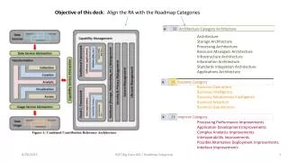
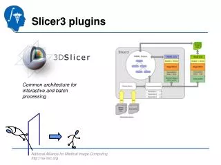
Slicer3 Architecture. NA-MIC Architecture. Scientist Desktop. Algorithms. ITK. Execution Model. Slicer Modules. Slicer 3.0. VTK. Experiment Control. Query Plot Visualize. Python/Tcl MATLAB…. Experiment Results. Workstation / Cluster / Grid. Databases Local / BIRN. Data

E N D
NA-MIC Architecture Scientist Desktop Algorithms ITK Execution Model Slicer Modules Slicer3.0 VTK Experiment Control Query Plot Visualize Python/Tcl MATLAB… Experiment Results Workstation / Cluster / Grid Databases Local / BIRN Data Acquisition
Slicer3 “Observer MVC” Pattern • MRML (Model) • For Scene Description and Application State • MRML Nodes are Persistent and Undoable • Scene and Nodes are Observable • Logic Encapsulate VTK and ITK Pipelines (Controller) • Observe MRML to Configure Pipelines • Help Create/Manage Nodes • No UI Components (no Widgets, Actors, Mappers, Renderers or RenderWindows) • GUI (View) • Observe and Edit MRML • Interact with User and Display Hardware GUI Renderers Widgets Edit Observe Logic Observe Edit Observe Edit MRML Nodes “Observe” means generic event mechanisms are used to pass information. “Edit” means code can directly call methods. Example: GUI can call methods in Logic classes,but Logic cannot call GUI methods. MRML cannot call Logic or GUI methods. There can be many observers for any event.
Slicer 3 Architecture Diagram (updated 2007-01-09) CommandLineModule Base (Managed by Base and communicates like other Modules) Auto-Generated GUIs from XML Descriptions Logic Links to: Base Logic, MRML GUI Links to: KWWidgets Logic Links to: ITK MRML VTK (except Rendering) GUI Links to: VTK Rendering KWWidgets Logic MRML Mediators Mediators Observe Modified Events MRML • Provides • Frames for Widgets, • Routing of User Events Formulates Command Line and passes data Observe Modified Events on Application State Edit Mrml Scene/Nodes Describe Input options (uses --xml option) Back-door to MRML with MRMLIDImageIO ITK IO Factory Library (Otherwise through files, command line options) • Registers GUI Event Observers Interactive Module • Execution Model Modules • build as executables or shared libraries • support –xml query Observe Modified Events Logic Links to: Base Logic ITK MRML VTK (except Rendering) GUI Links to: VTK Rendering KWWidgets Logic MRML Mediators Edit Mrml Scene/Nodes Slicer Daemoncommunication viaserver port • External Connections • Use socket connection directly (e.g. MATLAB) • Use slicerget/slicerget utilities(e.g. unu) • Notes: • All classes in the Logic directory should be able to run ‘headless’ without OpenGL or window system for scripting and testing • Base Logic and GUI contain transient application state (cursor location, focus, mrml scene connection…) • Persistent and Undoable state in MRML Nodes • Interactive Modules are ones which interact with the VTK scene and/or User events • Interactive Modules interact with 3D scene by creating objects in MRML scene (not by direct manipulation of the Renderer) • Logic classes encapsulate and manage internal vtk/itk pipelines and provide helper routines to create/manage nodes • GUI classes are implemented as KWWidget subclasses • Each Logic class defines Get/Set methods for internal state and Modified Events that GUI classes can Observe • Code in Base implements “first order” Node types (Volumes, Models, Transforms, Fiducials, Colors, etc). • Code in Modules provides application-specific extensions
SliceNode TransformNode VolumeNode XYToIJK Matrix Calculated by SliceLayerLogic Coordinates are Cell Centered (no VTK flip) From GUI Slicer3 Slice Coordinates RASToRAS Transforms SliceToRAS Matrix XYToSlice Matrix RASToIJK Matrix RAS to RAS Coordinates Slice Coordinates XY Image Space Coordinates In RenderWindow IJK = XYToIJK * XY IJK = RASToIJK * RASToRAS * SliceToRAS * XYToSlice * XY IJK Volume Coordinates
MRML Nodes: Persistent, Undoable State Logic: Encapsulate VTK Pipelines, Observe MRML Nodes GUI: Manage Widgets and Rendering; Manipulated Nodes and Logic; Observe Nodes and Logic Slice Management Volume Display Node Volume Node Foreground Slice Layer Logic Volume Display Node Volume Node Background Slice Layer Logic Slice Node Slice GUI Slice Logic Slice Composite Node
MRML Nodes: Persistent, Undoable State Logic: Encapsulate VTK Pipelines, Observe MRML Nodes GUI: Manage Widgets and Rendering; Manipulated Nodes and Logic; Observe Nodes and Logic Slice Management Volume Display Node Stores: Window/Level Lookup Table (Color Node) Transparency Threshold Volume Node Foreground Slice Layer Logic Volume Display Node Volume Node Background Slice Layer Logic Slice Node Slice GUI Slice Logic Slice Composite Node
MRML Nodes: Persistent, Undoable State Logic: Encapsulate VTK Pipelines, Observe MRML Nodes GUI: Manage Widgets and Rendering; Manipulated Nodes and Logic; Observe Nodes and Logic Slice Management Volume Display Node Stores: RAS Location of Slice (Origin and Orientation) Field of View Pixel Dimensions Volume Node Foreground Slice Layer Logic Volume Display Node Volume Node Background Slice Layer Logic Slice Node Slice GUI Slice Logic Slice Composite Node
MRML Nodes: Persistent, Undoable State Logic: Encapsulate VTK Pipelines, Observe MRML Nodes GUI: Manage Widgets and Rendering; Manipulated Nodes and Logic; Observe Nodes and Logic Slice Management Volume Display Node Stores: Volume IDs per Layer Opacity of Overlay Volume Node Foreground Slice Layer Logic Volume Display Node Volume Node Background Slice Layer Logic Slice Node Slice GUI Slice Logic Slice Composite Node
MRML Nodes: Persistent, Undoable State Logic: Encapsulate VTK Pipelines, Observe MRML Nodes GUI: Manage Widgets and Rendering; Manipulated Nodes and Logic; Observe Nodes and Logic Slice Management Volume Display Node Stores: Image Data IJKToRAS Matrix Name… Volume Node Foreground Slice Layer Logic Volume Display Node Volume Node Background Slice Layer Logic Slice Node Slice GUI Slice Logic Slice Composite Node
Pipeline with: vtkImageReslice vtkImageMapToWindowLevelColors vtkImageMapToRGBA MRML Nodes: Persistent, Undoable State Logic: Encapsulate VTK Pipelines, Observe MRML Nodes GUI: Manage Widgets and Rendering; Manipulated Nodes and Logic; Observe Nodes and Logic Slice Management Volume Display Node Volume Node Foreground Slice Layer Logic Volume Display Node Volume Node Background Slice Layer Logic Slice Node Slice GUI Slice Logic Slice Composite Node
MRML Nodes: Persistent, Undoable State Logic: Encapsulate VTK Pipelines, Observe MRML Nodes GUI: Manage Widgets and Rendering; Manipulated Nodes and Logic; Observe Nodes and Logic Slice Management Volume Display Node Volume Node Pipeline with: vtkImageBlend Foreground Slice Layer Logic Volume Display Node Volume Node Background Slice Layer Logic Slice Node Slice GUI Slice Logic Slice Composite Node
MRML Nodes: Persistent, Undoable State Logic: Encapsulate VTK Pipelines, Observe MRML Nodes GUI: Manage Widgets and Rendering; Manipulated Nodes and Logic; Observe Nodes and Logic Slice Management Volume Display Node Volume Node GUI: SliceControllerWidget (Menus, Scale, Buttons…) SliceViewer (RenderWidget, ImageMapper, ImageActor…) Foreground Slice Layer Logic Volume Display Node Volume Node Background Slice Layer Logic Slice Node Slice GUI Slice Logic Slice Composite Node
Undo Architecture for Slicer3 • Versioning “Commit Aside” Strategy Encapsulated within MRML • Store “Initial Scene” (from file) and “Delta Scenes” (scenes containing undoable changes) • Delta Scenes ‘are’ MRML Scenes • Some Nodes are Reference Nodes • Setting the MRML scene in the Application Logic causes the cascade of observer callbacks • => All Undoable operations must store their data as MRML nodes
Undo Implementation MRML Scene Undo Stack Initial Scene Delta1 Scene Delta2 Scene Saved Scene N1 N1 N2 N4 N4 N3 N5 N5