Download
1 / 31
310 likes | 460 Vues
EVLA Front-End CDR. Overview & System Requirements. Overview & System Requirements. Introduction to the EVLA Front-End Task EVLA vs. VLA Feeds Receivers System Requirements, including: System Temperatures Linearity Gain Flatness Polarization FE CDR Presentation Overview.

E N D
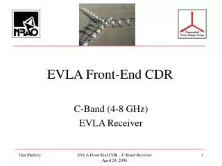
EVLA Front-End CDR Overview & System Requirements EVLA Front-End CDR - System Requirements 24 April 2006
Overview &System Requirements • Introduction to the EVLA Front-End Task • EVLA vs. VLA • Feeds • Receivers • System Requirements, including: • System Temperatures • Linearity • Gain Flatness • Polarization • FE CDR Presentation Overview EVLA Front-End CDR - System Requirements 24 April 2006
1.35 - 1.75 Lens + Corrugated 1 - (1.2) - 2 Compact Corrugated 2 - 4 Compact Corrugated 4.5 - 5.0 Lens + Corrugated 4 - 8 Compact Corrugated 8.0 - 8.8 Linear Taper Corrug 8 - 12 Linear Taper Corrug 14.4 - 15.4 Pyramidal 12 - 18 Linear Taper Corrug 18 - 26.5 Linear Taper Corrug 18 - 26.5 Linear Taper Corrug 26.5 - 40 Linear Taper Corrug 40 - 50 Linear Taper Corrug 40 - 50 Linear Taper Corrug VLA versus EVLA Band VLA EVLA Freq (GHz) Feed Horn Type Freq (GHz) Feed Horn Type L S C X Ku K Ka Q EVLA Front-End CDR - System Requirements 24 April 2006
1-(1.2)-2 2 – 4 4 – 8 8 – 12 12 – 18 18–26.5 26.5 – 40 40 - 50 26 26 26 30 37 59 53 74-116 12 12 10 10 12 25 13 26 - 68 14 14 16 20 25 34 40 48 QR+Hyb QR+Hyb QR+Hyb TBD PS+WB PS+WB PS+WB SS N/A N/A N/A N/A N/A 15–18 12–16.7 16.7-20 N/A N/A N/A N/A N/A x 2 x 3 x 3 1 – 2 2 – 4 4 – 8 8 – 12 12 – 18 8 – 16.5 8 – 18 8 - 18 -38 -35 -34 -32 -35 -38 -35 -38 40 38 33 29 27 23 21 15 T302 T302 T302 T304 T303 T303 T303 T303 1020 350 350 22 350 350 350 22 EVLA ReceiverOverview Band “L” “S” “C” “X” “Ku” “K” “Ka” “Q” Frequency (GHz) T(Sys) (°K) T(Sky) (°K) T(Rx) (°K) Polarizer Type LO Frequency (GHz) LO Multiplier Frequency Output Output Power (dBm) Headroom P1%(dB) Output to Module Refrigerator Model EVLA Front-End CDR - System Requirements 24 April 2006
Overview Table Notes T(Sky) (°K) : Antenna & atmosphere contribution when pointed at zenith in dry winter weather. Includes 3°K cosmic background T(Rx) (°K) : Averaged across full band, assumes LNA noise temperature of - 4°K below 4 GHz (Balanced Amplifiers) - 1°K/GHz 4-8 GHz & 0.5°K/GHz above 8 GHz. Polarizer Type : All dual circular polarization. - “QR+Hyb” = quad-ridge OMT followed by a 90 hybrid. - “PS+WB” = waveguide Srikanth Phase Shifter followed by Wollack’s implementation of a Bøifot class IIb OMT. - “SS” = Sloping Septum polarizer. LO Multiplier : The LO frequencies are multiplied by this factor in the receiver. Output Power : Total power contained in the output band specified while observing “cold sky” at zenith over the specified bandwidth. Headroom : With respect to the 1% compression point when on “cold sky”. Output to Module : RF/IF signal from receiver feeds the designated frequency converter module: T302 = LSC Converter , T303 = UX Converter , T304 = Down-Converter Refigerator Model : CTI Incorporated model numbers. EVLA Front-End CDR - System Requirements 24 April 2006
The Basic EVLA Receiver Plan • Provide Core Receiver Bands for every newly outfitted antenna • L, C, X(transition), K, Ka & Q-Band • Add brand new Future Receivers at a slower rate • S, X, Ku-Band EVLA Front-End CDR - System Requirements 24 April 2006
CDR ConsiderationsEVLA L-Band Receiver • The L-Band (1-2 GHz) front-end is the most critical EVLA receiver to be reviewed • Uses new octave bandwidth Circular Polarizer • Will be scaled for use in both the C and S-Band OMT’s (perhaps even X-Band) • The FE CDR has been delayed until the EVLA L-Band Prototype Receiver underwent preliminary evaluation • While waiting for completion of new EVLA design, “Interim” Rx’s are being installed on upgraded antennas • Modified with new EVLA balanced amplifiers • And 90 hybrid coupler polarizers • Delay is not affecting science capability with the EVLA and won’t until the wideband WIDA Correlator is available • Early tests start in late 2007 EVLA Front-End CDR - System Requirements 24 April 2006
CDR ConsiderationsEVLA K & Q-Band Receivers • K-Band (18-26.5 GHz) & Q-Band (40-50 GHz) receivers are upgrades to existing VLA systems • Design complete nearly 2 years ago & many of the production components have already been purchased • We will be reporting on what modifications have been adopted and results of systems now on the Array • Early systems installed on upgraded antennas use old VLA Card Cage and will need to be retrofitted at a later date to be EVLA compliant EVLA Front-End CDR - System Requirements 24 April 2006
CDR ConsiderationsEVLA C-Band Receiver • The new EVLA C-Band (4-8 GHz) receiver will use an octave bandwidth OMT scaled up in frequency from L-Band • Design not yet ready, so early C-Band receivers installed on upgraded antennas built as “Interim” systems • Uses commercial (Atlantic Microwave) 4.5-5.0 GHz Sloping Septum Polarizer, similar to the units used on the VLBA receivers • To keep pace with Antenna overhaul, at least six of these narrowband systems will be built • New C-Band system pioneers new the EVLA Common Dewar design which will be copied, as much as possible, by other new EVLA receivers (X, Ku & Ka-Band) • To save money, many of the C-Band microwave production components have already been purchased, except for the OMT EVLA Front-End CDR - System Requirements 24 April 2006
CDR ConsiderationsEVLA X-Band Receiver • As the VLA already has a decent (albeit narrowband) X-Band system, the EVLA will reuse the existing 8.0-8.8 GHz receiver until late in the Project. • This so-called “Transition” receiver can be mounted to either an old or a new X-Band feed. • Retaining an old receiver forces us to use the old Monitor & Control system. • A new 8-12 GHz system will be prototyped in 2008 with production scheduled for 2010, funds permitting. EVLA Front-End CDR - System Requirements 24 April 2006
CDR ConsiderationsEVLA Ka-Band Receiver • The Ka-Band (26.5-40 GHz) receiver provides a brand new discovery space for the VLA • Due to other pressures and diversions, the Ka-Band receiver development has been slow than planned • Straightforward “hybrid” of existing K & Q-Band receiver designs • Scaled K-Band Polarizer largely verified in the GBT 1cm receiver • Waveguide output similar to Q-Band • Uses novel MMIC-based down converter • Hope to complete design of prototype in 2006 • Production begins in 2007 EVLA Front-End CDR - System Requirements 24 April 2006
CDR ConsiderationsEVLA S, Ku & X-Band Receivers • S-Band (2-4 GHz) is a brand new receiver • Will be based on a scaled L-Band system • Prototype development to start in 2006 • Production begins in 2008 • New Ku-Band (12-18 GHz) will (eventually) replace the “crummy” existing VLA 14.4-15.4 GHz A-Rack system • Based on scaled K-Band system • Prototype development to start in 2007 • Production begins in 2010 • Ku-Band capability will be sacrificed as each antenna is outfitted • New EVLA X-Band design will cover 8-12 GHz • Polarizer design TBD • Prototype development to start in 2008 • Production begins in 2010 EVLA Front-End CDR - System Requirements 24 April 2006
Key: WR-28 Waveguide Cryogenic Dewar Coaxial Cable, 2.9mm Vacuum Window Coaxial Cable, SMA MMIC Module IF Post-Amp RF Post-Amp 25-41 GHz DC-18 GHz Cal Coupler 10 dB 15 dB 35 dB Quartz Window NF < 2.5 dB LNA NF < 5 dB Coax to WG RCP IF Output 8-18 GHz RCP x3 WG to Coax 2.9mm KaDCM 44-49 GHz OMT LO Ref 12-16.7 GHz @ 0 dBm Noise Diode Termination or Pulse Cal Input Magic Tee 90° Phase Shifter Transition 45° Twist Mylar Window 44-49 GHz KaDCM LCP IF Output 8-18 GHz WG to Coax 2.9mm x3 LCP Coax to WG NF < 5 dB NF < 2.5 dB 15 dB 10 dB 35 dB Quartz Window RF Post-Amp DC-18 GHz LNA 25-41 GHz IF Post-Amp Cal Coupler EVLA Ka-Band RxBlock DiagramRHH : 6 Jan 2005 EVLA Front-End CDR - System Requirements 24 April 2006
Estimated EVLA Ka-BandTRx, Output Power & Headroom EVLA Front-End CDR - System Requirements 24 April 2006
Summary of Estimated EVLA Front-End System Temperature, Output Power & Headroom EVLA Front-End CDR - System Requirements 24 April 2006
System Requirements The following slides present the Top Level System Requirements as specified in the EVLA Project Book Note that many of these requirements pertain directly to the performance of the entire Telescope system. Consequently, the contribution from the antenna optics, feeds & IF/LO systems may sometimes dominate the effects coming from the receivers. EVLA Front-End CDR - System Requirements 24 April 2006
System Polarization Characteristics(Project Book 2.2.2.5a) • Required: Over an 8 hour period, and under stable weather, the RCP and LCP polarization ellipses within the inner 3 dB of the antenna primary beam (FWHP) shall be stable to: • 0.002 in Axial Ratio • 2 degrees in Position Angle • Note : This is a mechanical stability issue, not only for the front-ends and feeds but for the entire antenna structure. The stability of the circular polarizers is likely to be very stable compared to the rest of the telescope. Unfortunately this spec is very hard, if not impossible, to measure in the lab. However, it can be done interferometricly with receivers on the Array. EVLA Front-End CDR - System Requirements 24 April 2006
Limits on Ellipticity(Project Book 2.2.2.5b) • Required: The RCP and LCP on-axis polarization ellipse (voltage) axial ratios are to be between 0.9 & 1.0 (or 0.92 dB) • Required: The axial ratios of the polarization ellipses are to be the same for all antennas at a given frequency, to within the same tolerances as given above. • Note :The polarization will undoubtedly be dominated by mismatches arising between the polarizer & the LNA’s or between other components along the input signal path. EVLA Front-End CDR - System Requirements 24 April 2006
System Temperature and Sensitivity(Project Book 2.2.3.1) • The indicated TSys values apply to the middle 50% of each band and include antenna, 3K Cosmic BG radiation, atmospheric absorption and emission when pointed at zenith in dry winter weather. • Required : Degradation of receiver temperature within any band with respect to the mean defined in the central 50% is to be by less than 3 dB at any frequency, by less than 1 dB over the inner 85% of each band, and by less than 2 dB over 95% of the band. • Note : Using conservative LNA noise temperature estimates suggests these receiver temperatures should, in general, be readily achieved. EVLA Front-End CDR - System Requirements 24 April 2006
14 12 26 14 12 26 16 10 26 20 10 30 25 12 37 34 25 59 40 13 53 48 26 - 68 74 - 116 EVLA Rx Band Noise Temperatures(Project Book 5.0) Band Treceiver (°K) † TSky (°K) ‡ TSystem (°K) L S C X Ku K Ka Q †Receiver temperature averaged across full band. ‡ Antenna, CBG & atmospheric contribution to TSys when pointed at zenith in dry winter weather. EVLA Front-End CDR - System Requirements 24 April 2006
VLA/EVLA Receiver Temperature Performance vs. Frequency Q-Av From Antenna 13, 14 & 16 EVLA Front-End CDR - System Requirements 24 April 2006 LNA’s : L & S @ 4K ; C @ 1K / GHz ; X, Ku, K, Ka & Q @ 0.5K/ GHz
Linearity of Power Gain to System Power Variations(Project Book 2.2.3.2 ) • Required : The following table gives the headroom requirements for the signal delivered to the sampler. The headroom is defined as the power ratio between the quiescent cold sky power and the power at which the 1 dB compression occurs. • Note : To mitigate the effects of RFI we want to operate 20 below the 1% compression point (which is 32 dB blow the P1dB compression point). • Note : These are requirements are for both the RF & IF systems.In general, the IF Chain compresses before the receiver (except at Q-Band). • Required : Changes in total system power monitored with an accuracy of better than 2% over an input power range between 15 and 50 dB above quiescent cold sky values. • Note : This applies only to receivers with the coupler-fed solar observing scheme. EVLA Front-End CDR - System Requirements 24 April 2006
BandpassCharacteristics (Project Book 2.2.3.4) a. Amplitude Stability • Required :Variations in bandpass (power units) are to be less than 1 part in 10,000 on timescales of less than 1 hour, on frequency scales less than the band frequency/1000. b. Phase Stability • Required : Phase variations within the bandpass are to be less than 0.006 degrees, on timescales less than 1 hour and frequency scales less than the RF frequency/1000. • Note : This is not the absolute total power stability of the RF/IF system but addresses bumps or dips appearing in the spectra of the correlator which could generate artifacts that look like absorption lines. At C-Band, the frequency scale is 5 MHz; at Q-Band it is45 MHz • Note : The spectral bandwidth & resolution needed to measure these on the Array will require the new WIDAR correlator. EVLA Front-End CDR - System Requirements 24 April 2006
Gain Slope(Project Book 2.2.3.4) c. Gain Slope • Required : The spectral power density slope at the input to the 3-bit sampler is to be less than 1.5 dB/GHz (or 3 dB across the full 2 GHz wide input). • Required : The spectral power density slope of the signals input to either the 3-bit or 8-bit samplers is to be less than: • i) 12 dB/MHz at L-Band • ii) 6 dB/MHz at S-Band • iii) 3 dB/MHz at C & X-Band • iv) 1.5 dB/MHz at Ku, K, Ka & Q band. d. Gain Ripples • Required : Fluctuations in the spectral power density about the mean slope are to be less than 4 dB, peak-to-peak, for signals input to the 3-bit digitizer. • Note : This is the peak-to-peak gain ripple remaining after the slope across the inner 90% of the 2-4 GHz digitizer input has been removed by the Gain Slope Equalizer system. They are relatively gernerous. EVLA Front-End CDR - System Requirements 24 April 2006
Gain Flatness and Passband Ripple(Project Book 3.2.3.3) • Required : The overall gain flatness of the EVLA FE/LO/IF system is specified as 5 dB over any 2 GHz bandwidth with a design goal of 3 dB over any 2 GHz bandwidth. These specifications have been divided as follows: • one-third to the Front-End • one-third to the T304 Downconverter • one-third to the 4/P, LSC and UX converter combination. • Note : This spec was only made possible by the adoption of the Gain Slope Equalizer scheme in the T304 Downconverter. • Required : Passband ripple is specified to be a maximum of 0.2 dB for ripple with a period less than 2 MHz. EVLA Front-End CDR - System Requirements 24 April 2006
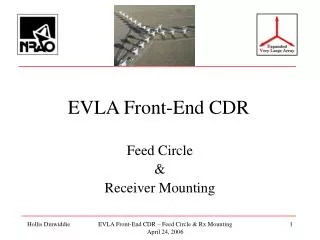
Overview of FE CDR Presentations Paul Lilie - OMT Development Lisa Locke - New L, S, X & Ku-Band Dan Mertely - New C-Band Bob Hayward - Upgraded K & Q -Band, New Ka-Band Chuck Kutz - Existing LF Receivers & EVLA LO/IF System Hollis Dinwiddie - Receiver Mounting Rudy Latasa - Cryogenic & Vacuum Systems Keith Morris - New Receiver Card Cage Wayne Koski - Receiver Monitor & Control Darrell Hicks - Vertex Cabin Infrastructure EVLA Front-End CDR - System Requirements 24 April 2006
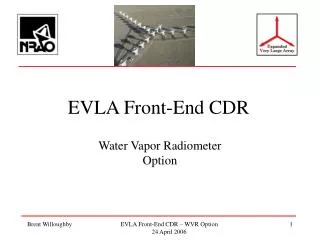
Overview of FE CDR Presentations Bob Hayward - Lab Receiver Testing Paul Lilie - Solar Mode Brent Willoughby - WVR Option Gerry Petencin - LNA Procurement Brent Willoughby - Receiver Production Bob Hayward - Project Schedule & Budget EVLA Front-End CDR - System Requirements 24 April 2006
Questions ? EVLA Front-End CDR - System Requirements 24 April 2006
Backup Slides EVLA Front-End CDR - System Requirements 24 April 2006
EVLA FeedsRolled Out View EVLA Front-End CDR - System Requirements 24 April 2006
EVLA Feed System All feeds are compact or linear taper corrugated horns with ring loaded mode converters Q Ka K Ku X C S L EVLA Front-End CDR - System Requirements 24 April 2006