Download
1 / 62
720 likes | 1.03k Vues
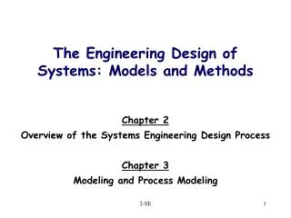
The Engineering Design of Systems: Models and Methods. Chapter 2 Overview of the Systems Engineering Design Process Chapter 3 Modeling and Process Modeling. The Big Picture. Functional Architecture. Operational Architecture. Physical Architecture. State Transition Diagram. Derived

E N D
The Engineering Design of Systems: Models and Methods Chapter 2 Overview of the Systems Engineering Design Process Chapter 3 Modeling and Process Modeling 2-SE
The Big Picture Functional Architecture Operational Architecture Physical Architecture State Transition Diagram Derived Requirements and Flowdown Interfaces Risk Analysis and Documentation 2-SE
Ch. 2 - Key Systems Terms see figure 2.1 • System – set of components acting together (SOI – system of interest) • System’s External systems – set of entities that interact via the external interfaces. • System’s Context – set of entities that can impact but not be impacted by the system. 2-SE
System/External Systems/Context External Systems Diagram Captures this Viewpoint 2-SE
Some Key Concepts • System’s inputs come from external systems or context. • All of system’s outputs flow to external systems. Play a role in establishing requirements 2-SE
Buede’s Observation • The design process, as presented, is not a ‘formal’ process. • Success and correctness cannot be proven or guaranteed. 2-SE
Six Main Steps of Design Process • Define the system level design problem. • Develop operational concept • Define system boundary and external systems diagram • Develop system objectives hierarchy • Develop, analyze, and refine requirements • Ensure requirements feasibility • Define test system requirements • Obtain approval of system documentation 2-SE
Six Main Steps of Design Process • Define the system level design problem. • Develop the system functional architecture • Develop the system physical architecture • Develop the system operational architecture • Develop the interface architecture • Define the qualification system 2-SE
This may appear to be a linear, sequential process….. • But it’s not. • Consider qualification early on, look ahead, look back, revise and refine. 2-SE
More Concepts and Terminology (Section 2.3) • ‘Operational Concept’ • Vision of the system – general terms • Mission requirements, How used • Set of operating scenarios 2-SE
Elevator Operational Concept See hand-out • Vision • Product and market background • Mission • Performance objectives • Operational Phase Scenarios • Text and ‘input/output trace’ summaries of scenarios 2-SE
Operating Scenario • In Systematica • ‘Functional Interactions’ between systems. • A collection of ‘Interactions’ becomes a ‘Feature’. • ‘Interactions’ happen in a state of the State Diagram. See Elevator Handout Input/Output Trace 2-SE
External Systems Diagram (ESD) • Defines the ‘boundary’ of our system • Where it starts and ends • Consistent with Operational Concept • Developed from the Operating Scenarios • Figure 2.2 – Elevator Example. Sometimes called : Domain or Context diagram 2-SE
Elevator System ESD 2-SE Figure 2.3 – IDEF0 modeling
Elevator Example Comments • Two slightly different versions of it • One in book & authors PPT slides. • One better and more detailed provided as a case study. 2-SE
External Systems & Context 2-SE Figure 2.1
Create a Graphical Model for the ESD • Integrated Definition for Functional Modeling – IDEF0. • Detailed in Chapter 3. • Boxes – functions, verb phrases • ICOM – inputs, controls, output, mechanisms. 2-SE
Hierarchical representation of major performance, cost, and schedule attributes. Define stakeholder satisfaction. Objectives Hierarchy 2-SE
Requirements • Define operational requirements – what we want the system to accept, do, and be. • Several approaches to Requirements – Ch. 6 • Carefully constructed written statements. 2-SE
Levels of Requirements Stakeholder Requirements Use our engineering skills and talents to create, develop, design Figure 6.1
Originating (Shareholder) Stakeholders agree with these. Written in English. System Translation of originating into engineering terms. Weight, speed, distance. Two levels of Requirements:Originating and System 2-SE
Four Categories of Requirements • Input/Output • Inputs, outputs, external interfaces, functional requirements. • Really important for describing system behavior • Technology and System Wide • ‘Technology’ in the system • ‘Ilities’ of the system • Cost, schedule 2-SE
Categories of Requirements • Trade-off Requirements • Performance, cost • Cost/performance • Algorithms to enable • System Qualification • How to obtain test data • Data used for design = real system • Data used for real system = originating reqs. • Data used for real system = stakeholders wants 2-SE
Verb Noun Noun Function • Process that changes inputs into outputs. • Describes ‘what’ not ‘how’ • Top level – single function • Sub-functions below 2-SE
Interfaces are critical • Connection resource • ‘Hook together’ components and external systems. • Interfaces have inputs, outputs, perform functions. • May be software, hardware, mechanical, electrical, etc. 2-SE
QualificationVerify/Validate/Accept • Qualification – means ‘test’ and an umbrella term for V&V • Verification – was system built right. • Validation – was right system built (meets scenarios and requirements). • Acceptance – stakeholders feel system meets their needs, acceptable. 2-SE
The Big Picture Functional Architecture Operational Architecture Physical Architecture State Transition Diagram Derived Requirements and Flowdown Interfaces Risk Analysis and Documentation 2-SE
The Big Picture 2-SE
This seems complicated – what about software tools ? • Buede suggests CORE Software • Many systems engineering software tools available. • Issues – learning curve, power, detail, flexibility, terminology, automation, etc. 2-SE
Let’s keep it simple • Microsoft Word, Excel, Visio 2-SE
Visio Software • Multipurpose drawing/flowcharting package. • Now part of Microsoft. • Shape oriented concept. • A good tool for engineers. 2-SE
Visio Demonstration? • Overview of basic features. • Shape stencils • Drag and drop shapes • Edit shape properties • Text • Tools : Alignment, Group, Rotate, etc. • Pages 2-SE
Ch. 3 – Modeling and IDEF0 • Models are abstractions of reality…. • Modeling languages – • Semantics – symbols, signs. • Syntax – rules for combining symbols. • Process models – input/function/output. • IDEF0 and others in Ch.12. 2-SE
External Systems & Context 2-SE Figure 2.1
MBSE • We will be learning ‘Model Based Systems Engineering’ (MBSE) • Building graphical models to depict system structure and behavior. • Far less dependent on volumes of written requirements. 2-SE
Models • Models are an abstraction…. • The essence of a model is the set of questions that the model can answer for us. 2-SE
The Truth About Models • Models are – • Incomplete, • Inaccurate, • Simplified, • Etc. All models are wrong, but some are useful. (George Box) 2-SE
Software’s love/hate thing with models • To agile people – just one more thing not to do if you don’t have to • To organizations with a well-defined way to convert requirements to models, etc. – the only way to go! (E.g., the Rational process.) • To organizations without that, doing one more routine project – something we wish we could try! • To organizations who are now facing a new kind of project – a dream / something new to try, if we have time! 2-SE
Types of Models • Physical • Mock-ups, • Scale models, • Prototypes, • Breadboards. • Questions: how much, visualization, scenario testing. 2-SE
Types of Models - 2 • Quantitative • Analytic, • Empirical, • Simulation • Static/dynamic, deterministic/stochastic. • Questions: How much, often, good, etc. 2-SE
Types of Models - 3 • Qualitative • Symbolic, • Text, • Graphic • Questions : what needs to be done, what order, etc. 2-SE
Types of Models - 4 • Mental • Abstractions of thought. • Highly useful, but hard to communicate. 2-SE
Potential Uses of Models • Create, specify, communicate, and test a shared vision. • Estimation and prediction of qualitative measures. • Selection of one option over another. Buede text emphasizes qualitative modeling. 2-SE
The SE Design Strategy • The ‘Onion’ concept • Primarily top-down • High level of Abstraction • Proceeding to • More and more detail and definition • Decomposition or modular approach 2-SE
IDEF0 Modeling • Section 3.3 – visit www.idef.com • Function box – Verb phrase, number. • Flow of material or data or information. • A-0 is the ‘ESD/context diagram’. • A0 is the top level function. • Decomposition 2-SE
Page Number(s) Page Content A - 1 Ancestor or external system diagram A - 0 Context or system function diagram (contains A0) A0 Level 0 diagram with first tier functions specified A1, A2, ... Level 1 diagrams with second tier functions specified A11, A12, ..., A21, ... Level 2 diagrams with third tier functions specified ... … IDEF0 Page Structure 2-SE Figure 3.5; Table 3.2