Download
1 / 13
130 likes | 350 Vues
Voltage Management of Low voltage (LV) Busbars. Plenary session B – Low voltage operation Dan Randles Quality of Supply and Technical Manager/LCNF Tier 1 Manager LCNF Conference October 2012. Aims and Objectives.

E N D
Voltage Management of Low voltage (LV) Busbars Plenary session B – Low voltageoperation Dan Randles Quality of Supply and Technical Manager/LCNF Tier 1 Manager LCNF Conference October 2012
Aims and Objectives • Aim is to trial solutions with potential to help voltage management on LV networks and to provide operators with understanding of the potential for alternative methods to cope with the changing nature of demands • ability to effectively manage voltages in real-time in a safe and economical manner will be assessed • effectiveness of devices to correct power factor will be assessed • Issues including phase imbalance and power quality to be assessed where appropriate supported by simulations • 30 month project started in April 2011 costing £0.5M
Scope • 6 sites selected for trials (11kV or 6.6kV) • Simulations used to explore numerous scenarios • PV clusters or high load areas (or both) • LV network monitoring deployed (Incl. PQAs) Edge Green • Dunton Green • Greenside • Landgate • Leicester Howard St
Network Monitoring (LVNS) • Scope of the deployment • 200 x 11kV or 6.6kV to 415V distribution substations • Over 1000 LV feeders • Sites comprise indoor and outdoor, mostly ground mounted with small number of pole mounted transformers • Analogues to be captured • RMS voltages and currents • Real and reactive power • 3ø + neutral • Temperature (Ambient, Tx) • Real-time (1 minute averages!) • Harmonics (not real time) GPRS/3G Private APN Metrology and Communications (V, I, Q, P, H, Temp)
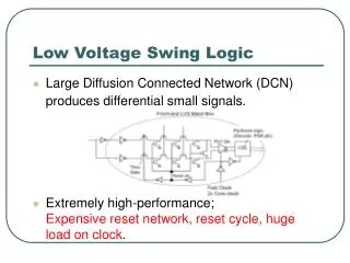
Trials • Three techniques were explored through field trials • Numerous more will be looked at through simulations • Field trials: • Substation (iebusbar) voltage regulation via OLTC distribution transformer • Harmonic filtering, power factor correction and phase balancing via active filter • In-line (ie LV feeder) voltage regulation via power optimizer • Field trials commenced in August 2012 and will continue for a period of 12 months • Too early in the trial stage to assess results but lots of valuable practical learning already obtained
Voltage Management – Active Harmonic Filters • As well as harmonic filtering the AHF provides load balancing and power factor correction • Technical details: • Active Filter Type PQFS – M10 amp • Voltage (V): 420V • Frequency (Hz): 50 • Total Current (A): 100 • Total Power (kVA): 71 • IP Rating - IP30 • Ambient Temperature -10oC/+40oC • Dimensions: W585 x D310 x H685 mm • ENW have installed the AHF at two locations in Manchester; 1 indoor and 1 outdoor • Full harmonic studies have been completed prior to the installation to ascertain background harmonic levels
Voltage Management – Power Perfector (PP+) • 320kVA rating • Voltage optimiser has the capability to adjust target volts • AVC available taps (+4%, 0%, -4%, -8%, -12%) and (+2.7%, 0%, -2.7%, -5.4%, -8.1%) • Operating temperature range: - 10oC/+50oC • Installed by-pass arrangement for trial
Voltage Management – On load Tap changing Distribution Transformer • x2 OLTC distribution transformers from Reinhausen of Germany (MR) • Technical details for the OLTC: • 500kVA rating • x1 unit at 11kV and x1 unit at 6.6kV • Tapping range - 8% to + 8% in 8 steps of 2% • Utilises the MR OLITAP mechanical tap changer • Tap changer incorporated within a ‘modified’ UK standard EFACEC Tx • Voltage control relay via TAPCON230 with DNP3 • Delivered in September 2012 installation scheduled for December • Fundamentals providing design and installation support for the AVC equipment AVC
Lessons learnt • Approvals, policies and authorisations • Customer impact must be minimised particularly noise and interruptions • True partnering approach with all project stakeholders • Academic support crucial to help make sense of results • Site surveys essential to avoid problems during installation • Installation quality including anti tamper/vandal • Network monitoring key to understanding the outcomes • Large volumes of data being generated which needs managing – requires new tools/systems
Network Modelling Extract Validate Analyse
Future solutions • The adoption at scale of low carbon technologies will have a significant impact on LV networks • Voltage rise/drop • Congestion/overload of assets • Monitoring is key to firstly understanding the capabilities of LV networks both now and in the future and secondly facilitating smart operation • Appears likely that active means of controlling voltages and loadings in LV networks will be implemented in the future • Significant change in operation and planning procedures for network operators • These techniques are introducing complexity into networks which are inherently simple – this represents a challenge to operators
Thank you • Any questions…?