Download
1 / 67
670 likes | 854 Vues
Chapter 5 Creating and Editing Drawing Views. Chapter 5 - Objectives. After completing this chapter, you will be able to Understand drawing options Create and edit drawing borders and title blocks Create base and projected drawing views from a part

E N D
Chapter 5 - Objectives • After completing this chapter, you will be able to • Understand drawing options • Create and edit drawing borders and title blocks • Create base and projected drawing views from a part • Create auxiliary, section, detail, broken, break-out, draft, and perspective views • Edit the properties and location of drawing views • Retrieve model dimensions to use in drawing views • Edit, move, and hide dimensions • Select drawing objects using a window or a crossing window • Add automated centerlines
Chapter 5 – Objectives continued • After completing this chapter, you will be able to • Add general dimensions • Add annotations such as GD&T, surface finish symbols, weld symbols, and datum identifiers • Create hole notes • Create chamfer notes • Open a model from a drawing to edit • Manage drawing sheets • Create baseline dimensions • Create ordinate dimensions • Create hole tables • Create general tables • Plot multiple drawing sheets
Drawing Options • Drawing Options • Retrieve Model Dimensions on View • Center dimension text on creation • Dimension Type • Object Style • View Justification • Display Options • Title Block Alignment
Creating a Drawing • Creating a Drawing • IDW file • Drawing Tools • Drawing Views • Sketch • Drawing Annotation
Creating a Drawing • Drawing Sheet Preparation • Default drawing sheet • Edit Sheet dialog box • Sheet Format • Custom Size
Border Creation • Border Creation • Four lines and zone labels • Default Border • Default Drawing Border Parameters dialog box • Sheet margins • Edit
Title Block Creation • Title Block Creation • Default Title Block • Drawing Properties dialog box • iProperties • Creating a New Title Block • Customized title block • Existing, from scratch or AutoCAD data • Title block
Title Block Insertion • Insert Title Block • Delete existing title block • Drawing Resources Folder
Title Block Fields • File iProperties tabs • Summary • Project • Status
Styles • Controlling Styles • Project File • Yes • Read Only • No • Styles Library • Format Menu • Active Standard • Styles Editor • Update Styles • Save Styles to Style Library • Purge Styles • Active Standard
Styles • Style Library • Central storage location of styles • Style in document takes precedence over a style library • Styles are filtered by the active standard • Local (cached) style in a document is always available for use
Styles • Create New Style • Styles Editor tool on the Format menu • Right-click the style on which the new style will be based and select New Style
Styles • Edit Styles • Click Styles Editor tool on the Format menu • Click the style you want to edit.
Styles • Set Object Defaults • Control how new objects will be formatted • Object Defaults option
Styles • Overriding an Object’s Style • Select objects • Select style from the Style drop list
Exercise 5-1 • Creating Text and Dimension Styles
Templates • Templates • Save your new drawing sheet, border, title block, drafting standard and dimension style as a template file • Save Copy As
Creating Drawing Views • Creating Drawing Views • Created from an existing part, assembly, or presentation file • Saving in same directory as the parent file • Types.. • Base View • Projected View • Orthographic (Ortho View) • ISO View • Auxiliary View • Section View • Detail View • Broken View
Creating Drawing Views • Component tab • File - Options change depending upon selected file • Presentation File • Sheet Metal • iAssemblies • Representations • Orientation • Scale from Base • Scale • Label • Style • Style from Base
Creating Drawing Views • Model State tab - Options change depending upon selected file • Weldment • iPart • Member (iAssemblies) • Reference Data • Line Style • Hidden Line Calculation • Margin • Scale • Label • Style
Creating Drawing Views • Options tab • All Model Dimensions • Model Weld Symbols • Bend Extents • Thread Feature • Weld Annotations • User Work Features • Tangent Edges • Foreshortened • Show Trails • Hatching • Align to Base • Definition in Base View • Section Standard Parts • View justification
Creating Drawing Views • Using the Drawing View Dialog Box • Base View • First view that is created • Scale • Other drawing views can be projected • Orientation - preview image • No limit to number of base views • Projected Views • Orthographic or isometric • From any existing view • Preview image • No limit
Exercise 5-2 • Creating a Multiview Drawing
Creating Drawing Views • Auxiliary Views • Created by selecting an edge • Normally projected at 90 degrees
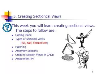
Creating Drawing Views • Section Views • Created by sketching a line or multiple lines that will define the plane(s) that will be cut through a part or assembly • Section View tool
Creating Drawing Views • Section Views • Half Sections • Aligned Sections • Offset Sections • Modifying Hatch • Right-click > Modify Hatch
Creating Drawing Views • Detail Views • Drawing view that enlarges an area of an existing drawing view by a specified scale • Detail View tool
Creating Drawing Views • Broken Views • Removes a section or multiple sections from the middle of a long part and show just the ends • Broken View tool
Creating Drawing Views • Break Out Views • Expose internal components or features • Break Out View tool • Boundary Profile
Creating Drawing Views • Break Out Views • Depth Options • From Point
Creating Drawing Views • Break Out Views • Depth Options • From Point • To Sketch
Creating Drawing Views • Break Out Views • Depth Options • From Point • To Sketch • To Hole
Creating Drawing Views • Draft Views • 2D Views • Parametric • Based on sketch(s)
Drawing View Options • Perspective View • Change View Orientation • Perspective views provide a realistic view of an assembly or component
Exercise 5-3 • Creating Broken, Section, Auxiliary, and Detail Views
Editing Drawing Views • Moving Drawing Views • Bounding box appears - rectangle • Children or dependent • Orthographic or auxiliary view • Detail and isometric views • Editing Drawing View Properties • Edit a drawing view • Drawing View dialog box • Deleting Drawing Views • Views that are dependent
Editing Drawing Views • Drawing View Alignment • Break associativity • Label Views • Realign Views • Horizontal • Vertical • In Position
Exercise 5-4 • Editing Drawing Views
Dimensions • Dimensions • Retrieve Model Dimensions • Edit and/or Change • Dimension Visibility • Dimension Value and Appearance • Drawing (Reference) Dimensions
Dimensions • Dimensions • Edit Model Dimension • Change Model Dimensions Value
Copy Dimension Properties • Style • Layer • Text • Precision and tolerance • Inspection • Arrowhead Shape • Arrowheads Inside / Outside
Annotations • Annotations • Adding • Centerlines • Surface texture symbols • Weld symbols • Geometric tolerance symbols • Text • Bill of materials • Balloons
Annotations • Centerlines • Center Mark • Center Line Bisector • Center Line • Centered Pattern tools • Automated Centerlines • Centerline Settings • Apply To • Threshold • View Types • Projection
Annotations • Adding more detail annotations • Surface Textures • Weld Symbols • Feature Control Frames • Text and Leaders • Format Text dialog box
Annotations • Text Positioning • Positioning text • Alignment • Vertical and horizontal • Offset • Apply a line-spacing value • Vertical and horizontal positions
Hole and Thread Notes • Adding… • Hole & Thread Notes • Hole Note Styles • Formatting • Apply tolerance values • Editing • Side Views
Exercise 5-5 • Adding Dimensions and Annotations
Opening a Model from a Drawing to Edit • Open file types • Part • Assembly • Presentation
Managing Drawing Sheets • New Sheets • Copy existing sheet